Clock circuitry, Sdi clock, Clock circuitry –6 – Altera SDI HSMC User Manual
Page 14: Sdi clock –6, Table 2–4
2–6
Chapter 2: Board Components
Clock Circuitry
© July 2009 Altera Corporation
Clock Circuitry
This section describes the board's clock inputs and outputs.
SDI Clock
You can generate the reference clocks from the host board, external video sources, and
external SDI sources. The output of the clock generator should be set up to produce a
frequency of 148.5 MHz or 148.5 MHz/1.001 (148.35 MHz). Outputs from the
differential buffer are available at SMA outputs and also at the HSMC connector. The
SMA outputs are provided for use as a low-jitter signal directed into a SERDES
reference clock input on the host board.
shows the SDI HSMC clocking diagram.
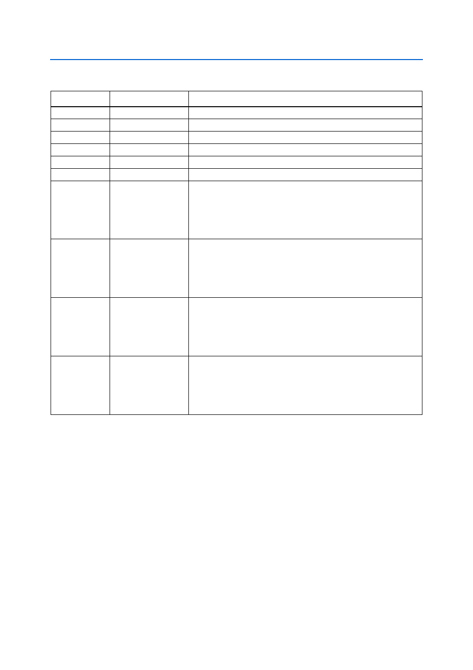
Table 2–4. LED Board References and Functional Descriptions
Board Reference Schematic Signal Name
Description
D2
—
Green LED. Illuminates when carrier is detected in channel 2.
D4
—
Green LED. Illuminates when carrier is detected in channel 1.
D7
—
Green LED. Illuminates when 3.3-V SDI power is active.
D8
—
Green LED. Illuminates when 3.3-V AES power is active.
D9
—
Green LED. Illuminates when 5-V power is active.
D12
—
Green LED. Illuminates when 3.3-V PLL power is active.
D1
SDI_LED_RX_G2
,
SDI_LED_RX_R2
Bi-color LED. Illuminates in:
■
Green when SDI_LED_RX_G2 signal is driven low.
■
Red when SDI_LED_RX_R2 signal is driven low.
■
Orange when both SDI_LED_RX_G2 and SDI_LED_RX_R signals are
driven low.
D3
SDI_LED_TX_G2
,
SDI_LED_TX_R2
Bi-color LED. Illuminates in:
■
Green when SDI_LED_TX_G2 signal is driven low.
■
Red when SDI_LED_TX_R2 signal is driven low.
■
Orange when both SDI_LED_TX_G2 and SDI_LED_TX_R2 signals
are driven low.
D5
SDI_LED_TX_G1
,
SDI_LED_TX_R1
Bi-color LED. Illuminates in:
■
Green when SDI_LED_TX_G1 signal is driven low.
■
Red when SDI_LED_TX_R1 signal is driven low.
■
Orange when both SDI_LED_TX_G1 and SDI_LED_TX_R1 signals
are driven low.
D6
SDI_LED_RX_G1
,
SDI_LED_RX_R1
Bi-color LED. Illuminates in:
■
Green when SDI_LED_RX_G1 signal is driven low.
■
Red when SDI_LED_RX_R1 signal is driven low.
■
Orange when both SDI_LED_RX_G1 and SDI_LED_RX_R1 signals
are driven low.