General information, General information –14 – Altera Stratix V Advanced Systems User Manual
Page 32
5–14
Chapter 5: Board Test System
The Power Monitor
Stratix V Advanced Systems Development Kit
February 2013
Altera Corporation
User Guide
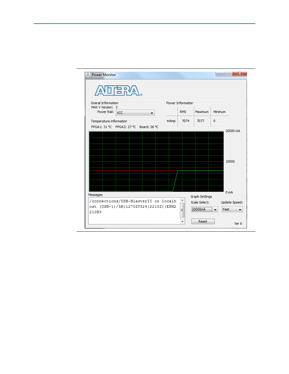
The Power Monitor communicates with the MAX V device on the board through the
JTAG bus. A power monitor circuit attached to the MAX V device allows you to
measure the power that each Stratix V GX FPGA device is consuming.
shows the Power Monitor.
The following sections describe the Power Monitor controls.
General Information
The General information controls display the following information about the
MAX V device:
■
MAX V version
—Indicates the version of MAX V code currently running on the
board. The MAX V code resides in the
revisions of this code might be available on the
page of the Altera website.
■
Power rail
—Selects the power rail to measure. After setting the Power rail list to
the desired rail, click Reset to refresh the screen with new board readings.
1
All rails use a 0.003 ohm resistor, except S5_VCC that uses 0.001 ohms.
Figure 5–7. The Power Monitor