Wiring, General wiring guidelines, 1 mechanical connection of the base modules – Pilz PSSu E S 2DOR 10 User Manual
Page 26: 6wiring, 1 general wiring guidelines
Pilz GmbH & Co. KG, Felix-Wankel-Straße 2, 73760 Ostfildern, Germany
Telephone: +49 711 3409-0, Telefax: +49 711 3409-133, E-Mail: [email protected]
6-1
6.1
General wiring guidelines
6
Wiring
6
6000
Wiring
Wiring
6-
6.1
General wiring guidelines
6100
General wiring guidelines
6-
][Verdrahtung BA Einleitung
Please note:
][Verdrahtung Ausgang Relais WARNUNG
][Verdrahtung ST-Ausgang Relais
The actuators may be connected using unshielded cables.
To prevent contact welding, a fuse should be connected before the
output contacts (see Technical details).
With inductive loads, sufficient fuse protection must be provided on
all output contacts.
Use copper wiring.
][Verdrahtung Zusatz mit C
The terminal configuration as stated on the front plate applies for base
modules with C-rail. The terminal configuration as stated in the tech-
nical documentation applies for all other base modules.
6.1.1
Mechanical connection of the base modules
Mechanical connection of the base modules
6-
][Modulverdrahtung mech
Procedure:
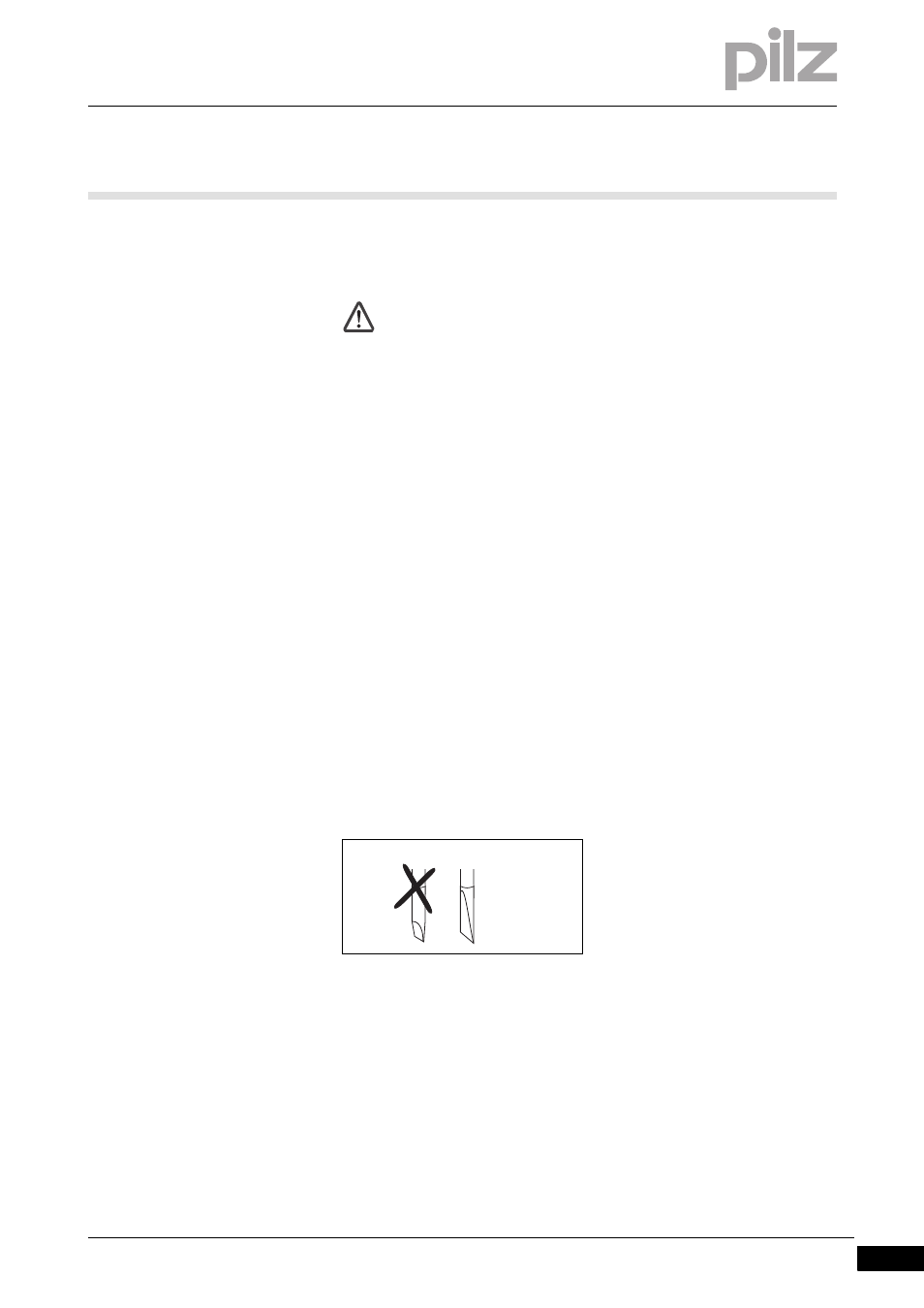
Use a flat blade screwdriver (DIN 5264-A)!
Strip the wire back 8 mm.
If necessary, label the connection level with a colour marker [3].
Base module with screw terminals:
– Use a screwdriver to loosen the screw on the screw terminal [1]
– Insert the stripped cable into the round fixing hole [2], as far as it
will go.
– Tighten up the screw on the screw terminal.
– Check that the cable is firmly seated.
WARNING!
Risk of electrocution!
With voltages higher than 50 VAC or 120 VDC at the relay con-
tacts, your life could be in danger if you touch conductive parts
on the module.
The C-rail of the supply group may only be connected to the
protective earth (PE).
DIN 5264-A