2 display elements, 1 display elements for module diagnostics, 2 display elements for an output's fs enable – Pilz PSSu E F 4DO 0.5 User Manual
Page 31: Display elements, Display elements for module diagnostics, Display elements for an output's fs enable
Operation
Operating Manual PSSu E F 4DO 0.5(T)(R)
21316EN05
31
7.2
Display elements
Legend:
LED on
LED off
7.2.1
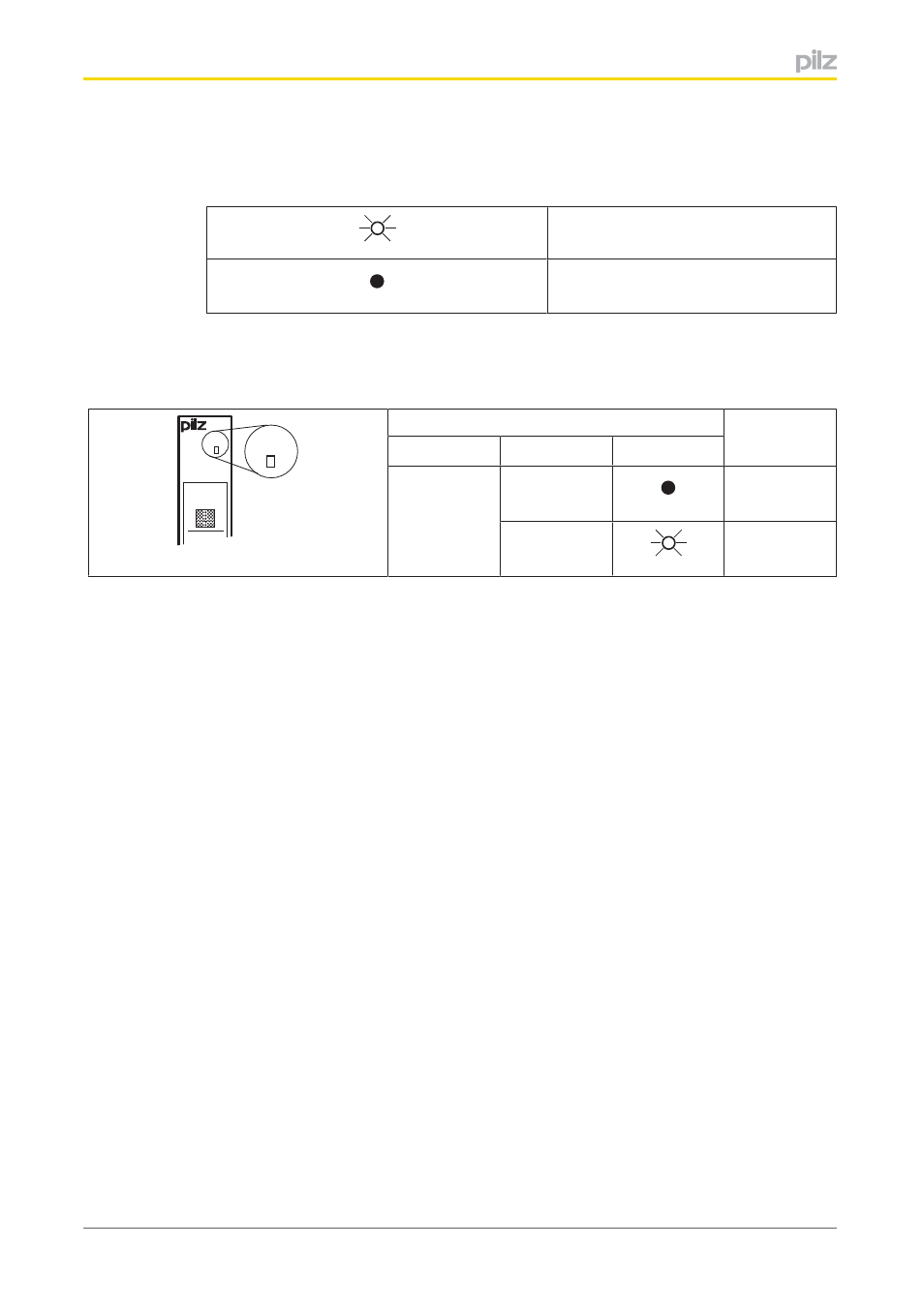
Display elements for module diagnostics
The module has an LED for displaying module errors ("Err" LED).
Err
11
I0
21
I1
Err
LED
Meaning
Name
Colour
Status
Err
No error
Red
Module error
7.2.2
Display elements for an output's FS enable
With the local enable principle (system environment A) or the enable principle (system en
vironment B), FS outputs are activated via an ST section. An FS enable is assigned to each
of these FS outputs. The status of that enable is displayed via the enable LEDs (“FS0”,
“FS1”, “FS2” and “FS3”).
This manual is related to the following products: