6 commissioning, 1 wiring, 1 general wiring guidelines – Pilz PNOZ m ES Profibus User Manual
Page 15: 2 connecting the supply voltage, 3 profibus dp interface, Section 6, Commissioning, Wiring, General wiring guidelines, Connecting the supply voltage
Commissioning
Operating Manual PNOZ m ES Profibus
1002698EN03
15
6
Commissioning
6.1
Wiring
6.1.1
General wiring guidelines
The wiring is defined in the circuit diagram of the PNOZmulti Configurator.
Note:
}
Information given in the "Technical details" must be followed.
}
Always connect the mounting rail to the protective earth via an earthing terminal. This
will be used to dissipate hazardous voltages in the case of a fault.
}
The power supply must meet the regulations for extra low voltages with protective sep
aration.
6.1.2
Connecting the supply voltage
Connect the supply voltage to the fieldbus module:
}
Terminal 24 V: + 24 V DC
}
Terminal 0 V: 0 V
6.1.3
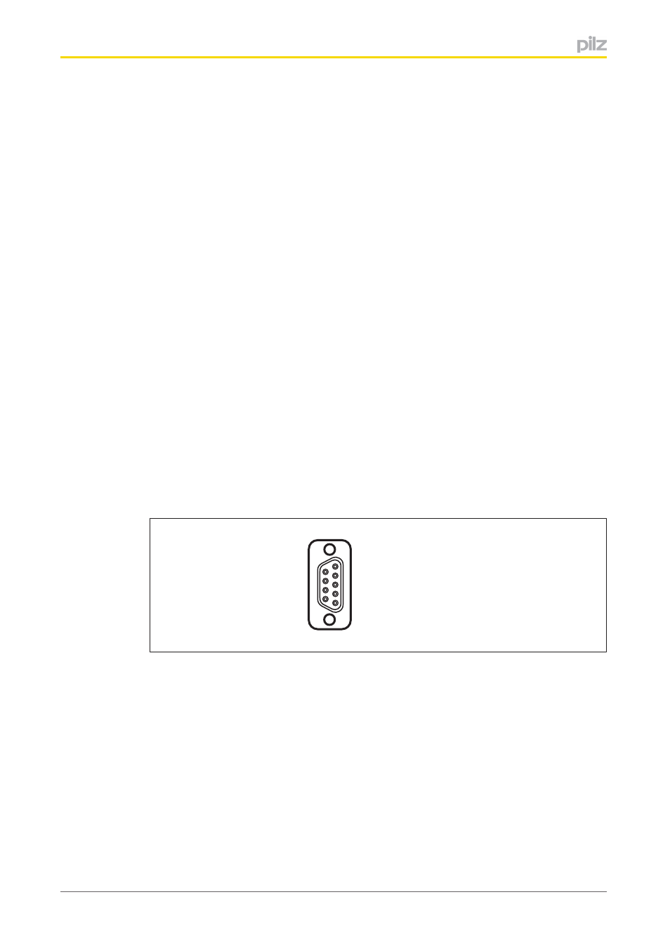
PROFIBUS DP interface
It is possible to define which outputs on the control system will communicate with
PROFIBUSDP. The connection to PROFIBUSDP is made via a female 9pin DSub con
nector in accordance with the guidelines of the PROFIBUS User Group (PNO).
1
5
9
6
1: n.c.
2: n.c.
3: B (RxD/TxD-P)
4: CNTR-P
5: DGND
6: VP
7: n.c.
8: A (RxD/TxD-N)
9: n.c.
n.c. = not connected
Please note the following when connecting to PROFIBUSDP:
}
Only use metal plugs or metallised plastic plugs
}
Twisted pair, screened cable must be used to connect the interfaces