4 block diagram, Block diagram – Pilz PNOZ m ES Profibus User Manual
Page 12
Function description
Operating Manual PNOZ m ES Profibus
1002698EN03
12
4.3
Assigning the inputs/outputs in the PNOZmulti Configurator
to the PROFIBUSDP inputs/outputs
Virtual inputs and outputs can be requested or set directly via the following objects. Each
element can be selected individually in the master control system, e.g. virtual inputs i031.
The data width is also established this way.
Input data
The Master writes to the virtual inputs of the PNOZmulti 2.
Description
Input data from PNOZmulti 2
Virtual inputs i0 – i31
4 Input Bytes
Virtual inputs i32 – i63
4 Input Bytes
Virtual inputs i64 – i95
4 Input Bytes
Virtual inputs i96 – i127
4 Input Bytes
Output data
The Master reads the virtual outputs of the PNOZmulti 2.
Description
Output data from PNOZmulti 2
Virtual outputs o0 – o31
4 Output Bytes
Virtual outputs o32 – o63
4 Output Bytes
Virtual outputs o64 – o95
4 Output Bytes
Virtual outputs o96 – o127
4 Output Bytes
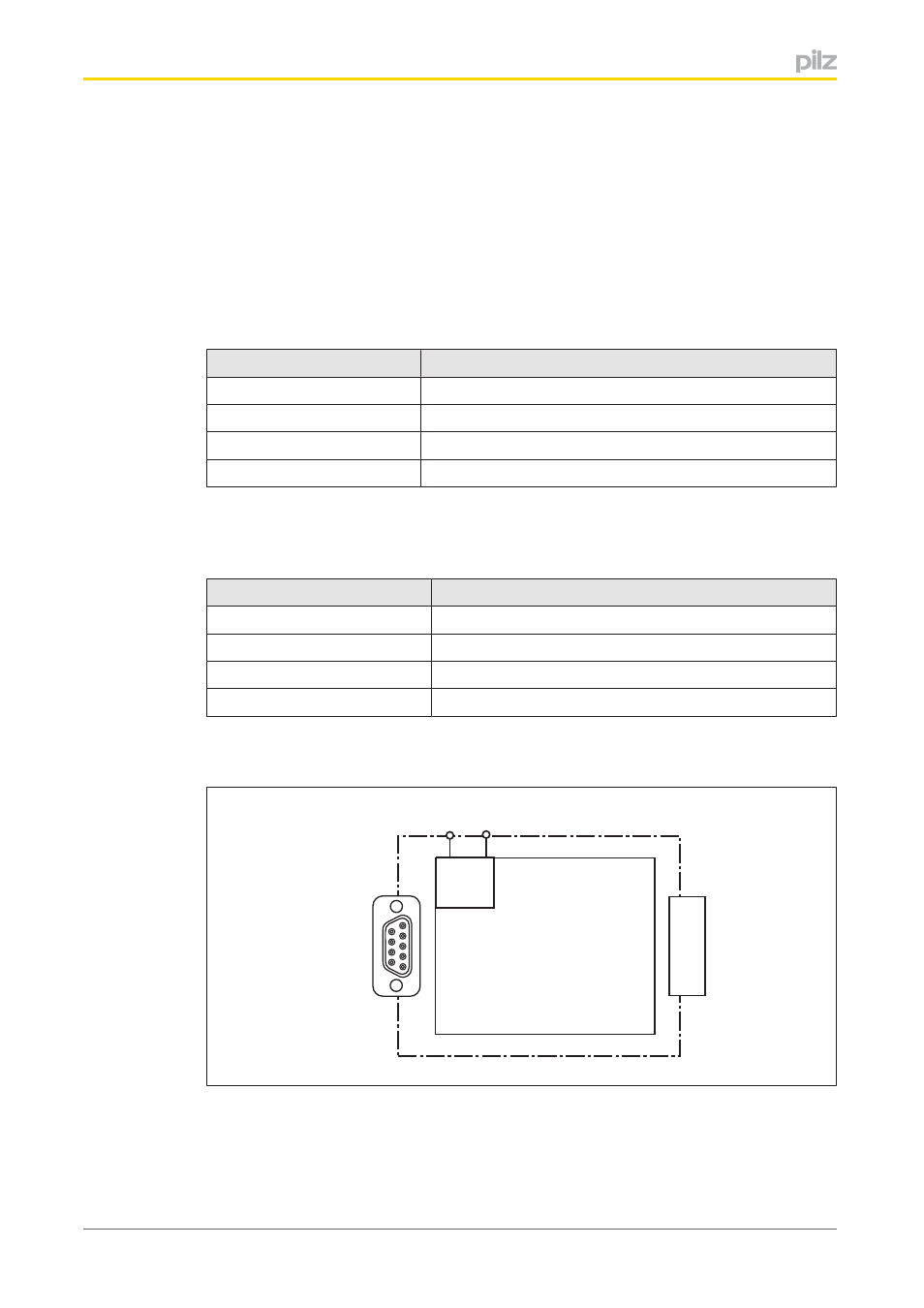
4.4
Block diagram
Base unit
PROFIBUS DP
24 V 0 V
24 V 0 V
- PSEN in1p (16 pages)
- PSEN in1n (12 pages)
- PSEN rs2.0-300 (16 pages)
- PSEN rs1.0-175 (16 pages)
- PSEN enc m1 eCAM (46 pages)
- PSENme 1S / 1AS (16 pages)
- PSENme 1S / 1AS (6 pages)
- PSENme 2 / 2A (6 pages)
- PSENme 4 / 4A (5 pages)
- PSEN 1.1a-20/PSEN 1.1-20 /8mm/5m/1unit (6 pages)
- PSEN 1.2p-25/PSEN 1.2-20/8mm/ATEX/ix1 (8 pages)
- PSEN 1.1a-22/PSEN 1.1-20 /8mm/5m/ix1/1un (6 pages)
- PNOZ m EF 2MM (6 pages)
- PNOZ m EF 2MM (6 pages)
- PSEN 1.1b-23/PSEN1.1-20/8mm/10m/EX/1unit (8 pages)
- PNOZ m EF 2MM (8 pages)
- PSEN 1.1p-20/PSEN 1.1-20/8mm/ 1unit (6 pages)
- PSEN 1.1p-29/PSEN 1.1-20/7mm/ix1/ 1unit (6 pages)
- PSEN 1.1b-25/PSEN1.1-20/8mm/10m/EX/1unit (8 pages)
- PSEN 1.1p-22/PSEN 1.1-20/8mm/ix1/ 1unit (6 pages)
- PSEN 1.1-10 / 1 actuator (6 pages)
- PSEN 1.2p-20/PSEN 1.2-20/8mm/ 1unit (6 pages)
- PSEN 1.1p-23/PSEN 1.1-20/8mm/ATEX/ 1unit (8 pages)
- PNOZ m EF 2MM (6 pages)
- PSEN 1.2p-22/PSEN 1.2-20/8mm/ix1/ 1unit (6 pages)
- PSEN 1.1p-25/PSEN 1.1-20/8mm/ATEX/ix1 (8 pages)
- PSEN 1.1-10 / 1 actuator (6 pages)
- PSEN 1.2p-23/PSEN 1.2-20/8mm/ATEX/ 1unit (8 pages)
- PSEN ma1.3a-20/PSEN ma1.3-08/8mm/1unit (10 pages)
- PSEN ma1.3a-22/PSEN ma1.3-08/8mm/1unit (10 pages)
- PSEN ma1.3b-23/PSEN ma1.3-08/8mm/1unit (10 pages)
- PSEN ma1.3b-25/PSEN ma1.3-08/8mm/1unit (10 pages)
- PSEN ma1.3p-20/PSEN ma1.3-08/8mm/1unit (10 pages)
- PSEN ma1.3p-22/PSEN ma1.3-08/8mm/ix1/1un (10 pages)
- PSEN ma1.3-20 M12/8-0.15m 1switch (10 pages)
- PSEN ma1.3n-20/PSEN ma1.3-08/8mm/1unit (12 pages)
- PSEN ma1.4p-52/PSEN ma1.4-03mm/ 1unit (10 pages)
- PSEN ma1.4p-51/PSEN ma1.4-03mm/ 1unit (10 pages)
- PSEN ma1.4-51 M12/8-0.15m 1switch (10 pages)
- PSEN ma1.4n-51/ 1switch (9 pages)
- PSEN ma1.4n-50/PSEN ma1.4-03mm/ 1unit (10 pages)
- PSEN ma1.4p-57/PSEN ma1.4-10mm/ 1unit (10 pages)
- PSEN ma1.4a-52/PSEN ma1.4-03mm/ 1unit (10 pages)
- PSEN ma1.4a-51/PSEN ma1.4-10mm/ 1unit (10 pages)
- PSEN ma1.4p-50/PSEN ma1.4-03mm/ 1unit (10 pages)