Funktionsbeschreibung, Montage, Description du fonctionnement – Pilz PNOZ po3.3p 3n/o User Manual
Page 2: Function description, Installation
- 2 -
PNOZpower-Bus
K1
K2
PNOZpower-Bus
Eingangskreise
Input circuit
circuit d'entree
Rückführkreis
feedback control loop
boucle de retour
Externer
Start/Stopp-Eingang
External start/stop input
Entrée Start/stop externe
L1
1
L2
3
L3
5
2
T1
4
T2
6
T3
Y39
Y40
*
Das Schaltgerät erfüllt folgende Sicherheits-
anforderungen:
• Schaltung ist redundant mit Selbstüberwa-
chung aufgebaut (EN 954-1 Kategorie 4).
• Sicherheitseinrichtung bleibt auch bei
Ausfall eines Bauteils wirksam.
• Bei jedem Ein-Aus-Zyklus der Maschine
wird automatisch überprüft, ob die
Ausgangskontakte der Sicherheitseinrich-
tung richtig öffnen und schließen.
Funktionsbeschreibung
Das PNOZ po3.3p stellt 3 Sicherheits-
kontakte für das modulare Sicherheitssystem
PNOZpower zur Verfügung. Es dient
zusammen mit den Basisgerät dem sicher-
heitsgerichteten Unterbrechen eines
Sicherheitsstromkreises. Die Sicherheits-
kontakte werden vom Basisgerät angesteu-
ert. Versorgungsspannung, Eingangskreise
und Rückführkreis werden über den
PNOZpower-Bus geführt.
Sobald die
• Versorgungsspannung anliegt (LED
"POWER" leuchtet),
• der externe Start-/Stopp-Eingang Y39-Y40
geschlossen ist
• und die Eingangskreise 1 und 2 am
Basisgerät geschlossen sind,
gehen die beiden Ausgangsrelais K1 und K2
in Arbeitsstellung. Die Sicherheitskontakte
1(L1)-2(T1), 3(L2)-4(T2) und 5(L3)-6(T3)
schließen. Die LEDs "CH. 1" und "CH. 2"
leuchten.
Öffnen der Eingangskreise am Grundgerät
oder des externen Start-/Stoppeingangs
Y39-Y40:
Die zwangsgeführten Sicherheitskontakte
1(L1)-2(T1), 3(L2)-4(T2) und 5(L3)-6(T3)
öffnen.
Öffnen der Eingangskreise am Grundgerät:
Die LEDs "CH. 1" und "CH. 2" erlöschen.
Öffnen des externen Start-/Stoppeingangs
Y39-Y40: Die LED "CH. 2" erlischt.
Montage
• Das Sicherheitsschaltgerät muss in einen
Schaltschrank (min. IP54) eingebaut
werden. Zur Befestigung auf einer
Tragschiene dienen vier Rastelemente auf
der Rückseite des Geräts.
• Montieren Sie das Gerät auf eine waag-
rechte Tragschiene. Bei anderen Einbau-
lagen können die in den techn. Daten
angegebenen Werte für das Schalt-
vermögen nicht eingehalten werden.
• Das Erweiterungsmodul PNOZ po3.3p
kann an beliebiger Stelle des modularen
Sicherheitssystems PNOZpower montiert
werden.
Le relais satisfait aux exigences de sécurité
suivantes :
• Commutation redondante avec
autosurveillance (EN 954-1, catégorie 4).
• Le dispositif de sécurité reste actif, même
en cas de défaillance d’un composant.
• L’ouverture et la fermeture correctes des
contacts de sortie d`aprés du dispositif de
sécurité sont contrôlées automatiquement
à chaque cycle marche/arrêt de la
machine.
Description du fonctionnement
Le PNOZ po3.3p propose 3 contacts de
sécurité pour le système de sécurité
modulaire PNOZpower. Utilisé avec l’appa-
reil de base, il sert à interrompre de manière
sûre un circuit de sécurité. Les contacts de
sécurité sont commandés par l’appareil de
base. La tension d’alimentation, les circuits
d’entrée et la boucle de retour dépendent du
bus PNOZpower.
Dès que
• la tension d’alimentation est appliquée
(LED “POWER” allumée)
• le circuit externe Stat/stop Y39/Y40 est
fermé
• et que les circuits d’entrée de l’appareil de
base sont fermés,
les deux relais de sortie K1 et K2 passent en
position de travail. Les contacts de sécurité
1(L1)-2(T1), 3(L2)-4(T2) et 5(L3)-6(T3) se
ferment. Les LEDs “CH. 1” et “CH. 2”
s’allument.
Si l’un des circuits d’entrée des circuits
d’entrée ou le circuit stat/stop externe Y39-
Y40 :
Les contacts de sécurité à contact liés 1(L1)-
2(T1), 3(L2)-4(T2) et 5(L3)-6(T3) s’ouvrent.
Si l’un des circuits d’entrée : Les LEDs “CH.
1” et “CH. 2” s’éteignent.
Si l’un le circuit stat/stop externe Y39-Y40 :
Les LED “CH. 2” s’éteint.
The relay conforms to the following safety
requirements:
• The circuit is redundant, with built-in self-
monitoring (EN 954-1, Category 4).
• The safety function remains effective in the
case of a component failure.
• The correct opening and closing of the
output contacts is tested automatically in
each on-off cycle.
Function Description
The PNOZ po3.3p provides 3 safety
contacts for the PNOZpower modular safety
system. Together with the base unit, it
provides safety related cut-out of a safetycir-
cuit. The base unit controls the safety
contacts. Power supply, input circuits and
feedback loop are fed via the PNOZpower
bus.
As soon as
• the power supply is detected (the “PO-
WER” LED lights)
• the external start/stop input Y39-Y40 is
closed
• and the input circuits 1 and 2 on the base
unit made,
both output relays K1 and K2 are operational.
The safety contacts 1(L1)-2(T1), 3(L2)-4(T2)
and 5(L3)-6(T3) close. The LEDs “CH. 1”
and “CH. 2” illuminate.
The input circuits on the base unit or the
external start/stop input Y39-Y40 become
open:
The positive-guided safety contacts 1(L1)-
2(T1), 3(L2)-4(T2) und 5(L3)-6(T3) open.
The input circuits on the base unit become
open: The LEDs “CH. 1” and “CH. 2” go out.
The external start/stop input Y39-Y40
becomes open: The LED "CH. 2” goes out.
Installation
• The safety relay must be installed in a
control cabinet (min. IP54). There are four
notches on the back of the unit for DIN rail
attachment.
• Fit the unit to a horizontal DIN rail. In other
mounting positions, the values given in the
technical details for the switching capability
may not be achieved.
• The PNOZ po3.3p expander module can
be installed in any position on the
PNOZpower modular safety system.
• There are 2 sockets on the rear of the
PNOZ po3.3p. Connect the PNOZ po3.3p
Montage
• Le relais de sécurité doit être monté dans
une armoire avec, au minimum, l’indice de
protection IP54. Sa face arrière, dotée de
4 ergots, peut s’encliqueter sur un profilé
support.
• Montez l’appareil sur un profilé support
horizontal. Les autres positions de
montage ne permettent pas de respecter
les valeurs de commutation indiquées
dans les caractéristiques techniques.
• Le module d’extension PNOZ po3.3p peut
être installé en n’importe quel point du
système de sécurité modulaire
PNOZpower.
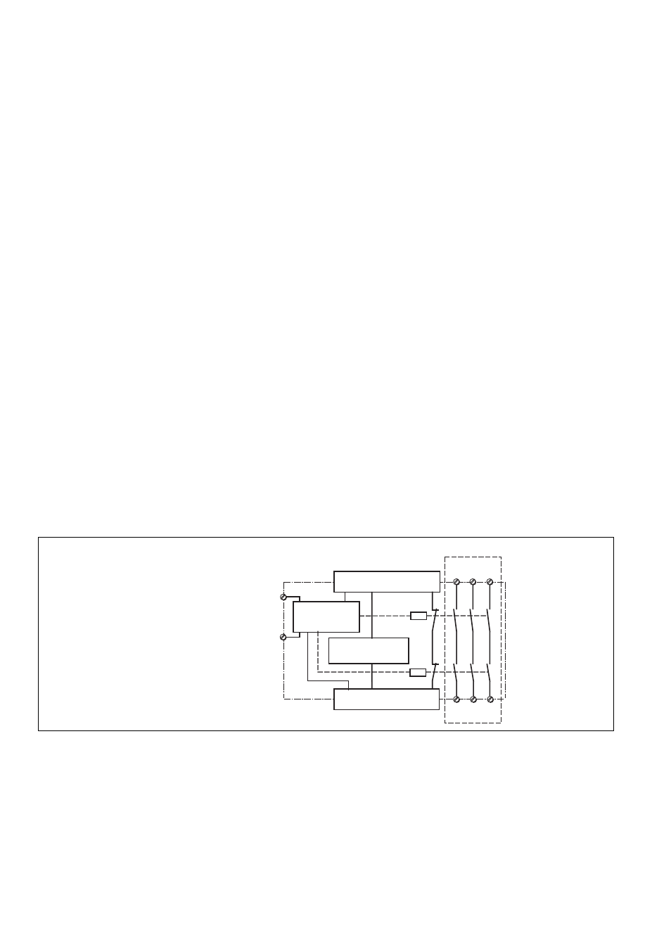
Fig. 1: Innenschaltbild/Internal Wiring Diagram/Schéma de principe
*Sichere Trennung nach EN 60947-1, 6 kV/*Safe separation in accordance with EN 60947-1, 6 kV/
*Séparation galvanique selon EN 60947-1, 6 kV