Pilz PNOZ e4.1p 24VDC 2so User Manual
Page 5
- 5 -
S21
S22
S11
S12
rot/red/rouge
schwarz/black/noir
schwarz/black/noir
rot/red/rouge
Y4
A1
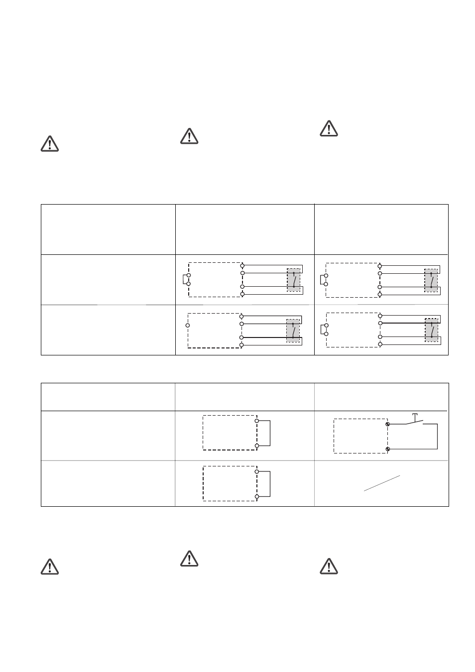
Eingangskreis
Input circuit
Circuit d’entrée
UND-Verknüpfung und ODER-Verknüpfung
aktiv
AND connection and OR connection active
Fonction logique ET ou fonction logique OU
active
keine Verknüpfung oder nur ODER-
Verknüpfung aktiv
No connection or just OR connection active
pas de fonction logique active ou seulement
la fonction logique OU
Ansteuerung einer PSS
Controlling a PSS
Pilotage d’un PSS
Ansteuerung eines PNOZelog-Geräts
Controlling a PNOZelog unit
Pilotage d’un appareil PNOZelog
S21
S22
S11
S12
rot/red/rouge
schwarz/black/noir
schwarz/black/noir
rot/red/rouge
Y4
S11
S21
S22
S11
Y4
S12
rot/red/rouge
schwarz/black/noir
schwarz/black/noir
rot/red/rouge
S21
S22
S11
S12
rot/red/rouge
schwarz/black/noir
schwarz/black/noir
rot/red/rouge
Y4
S21
Betriebsbereitschaft herstellen
• Verdrahten Sie die Versorgungspannung:
Klemme A1(+) : + 24 V DC
Klemme A2(-) : 0 V
• Verdrahten Sie die Schaltmatte mit den
Eingängen und legen Sie durch die Ver-
drahtung von Y4 fest, ob Sie
- die UND/ODER-Eingänge des
PNOZ e4.1p verwenden
und ob
- das PNOZ e4.1p mit seinen Ausgängen
eine PSS oder ein PNOZelog-Gerät
ansteuert.
Achtung! An Ausgänge, die eine
PSS ansteuern, dürfen keine
zusätzlichen Lasten angeschlossen
werden.
Sollen ausschließlich Schütze angesteuert
werden, empfehlen wir die Verdrahtung wie
bei der Ansteuerung der PSS.
• Stellen Sie die Rückstelleigenschaften
durch Verdrahten des Startkreises ein.
S34
S3
A1
S34
S21
S34
S11
Eingangskreis
Input circuit
Circuit d’entrée
Schaltmatte ohne Anlauftest
Safety mat without start-up test
Tapis sensible sans test des conditions
initiales
Schaltmatte mit Anlauftest
Safety mat with start-up test
Tapis sensible avec test des conditions
initiales
Automatische Rückstellung (Start)
Automatic reset (start)
Réarmement automatique (Start)
Manuelle Rückstellung (Start)
Manual reset (start)
Réarmement manuel (Start)
• Schließen Sie den Rückführkreis, indem
Sie Y6-A1 brücken oder die Kontakte
externer Schütze zwischen Y6 und A1
anschließen.
Achtung! Schließen Sie nicht die
Kontakte der externen Schütze in
Reihe zum Startkreis an.
Der Rückführkreis wird überwacht. Späte-
stens 150 ms nach dem Ausschalten des
Ausgangs muss der Rückführkreis wieder
geschlossen sein.
Preparing for operation
• Connect the supply voltage:
Terminal A1(+) : +24 V DC
Terminal A2(-) : 0 V
• Connect the safety mat to the inputs and
define via the wiring of Y4 whether
you are:
- using the AND/OR inputs of the
PNOZ e4.1p
and whether
- the PNOZ e4.1p is controlling a PSS
or a PNOZelog unit with its outputs.
Caution! No additional loads may be
connected to outputs that are used to
control a PSS.
If contactors alone are being controlled, we
recommend the wiring for controlling a PSS.
• Close the feedback loop by linking Y6-
A1 or by connecting contacts from
external contactors between Y6 and A1.
Caution! Do not connect the
contacts from external contactors in
series to the reset circuit.
The feedback loop is monitored. The
feedback loop must be closed no later than
150 ms after the output has switched off.
• Set the reset features via the wiring of the
reset circuit.
Mise en route
• Raccordez la tension d’alimentation :
Borne A1(+) : +24 V DC
Borne A2(-) : 0 V
• Raccordez le tapis sensible aux entrées
et déterminez à l’aide de Y4 si vous
voulez utiliser
- les entrées ET/OU du PNOZ e4.1p
et si
- le PNOZ e4.1p commande un PSS ou
un appareil PNOZelog par ses sorties.
Attention ! Les sorties qui
commandent un PSS ne doivent pas
être raccordées à d’autres charges.
S’il y a lieu de raccorder exclusivement des
relais, nous recommandons le même
raccordement que pour la commande d’un
PSS.
• Déterminez le type de réarmement par
câblage du circuit de réarmement
• Raccordez la boucle de retour, en
pontant Y6-A1 ou en raccordant les
contacts de relais externes entre
Y6 et A1 .
Attention ! Ne raccordez pas les
contacts des relais externes en série
avec le circuit de réarmement.
La boucle de retour est surveillée. Au plus
tard 150 ms après le déclenchement de la
sortie correspondante, la boucle de retour
doit être refermée.