Pilz PNOZ e3vp 10/24VDC 1so 1so t User Manual
Page 5
- 5 -
S34
S3
A1
S34
S23
S34
S11
• Verdrahten Sie den Rückführkreis und
stellen Sie die Verzögerungszeit ein.
Klemmen Y6 und Y7 dienen sowohl für
den Anschluss des Rückführkreises als
auch für die Programmierung der
Verzögerungszeit.
- Wenn beide Funktionen benötigt
werden, müssen immer zuerst die
Kontakte des Rückführkreises an Y6
und Y7 angeschlossen werden.
- Das Signal für die Programmierung der
Verzögerungszeit wird an den Kontakt
des Rückführkreises angeschlossen.
• Stellen Sie die Verzögerungszeit t
v
entsprechend folgender Tabelle ein (siehe
auch Anschlussbeispiel):
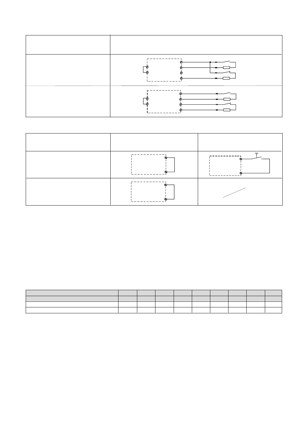
Eingangskreis
Input circuit
Circuit d’entrée
Schutztür ohne Anlauftest
Safety gate without start-up test
Protecteur mobile sans test des conditions
initiales
Schutztür mit Anlauftest
Safety gate with start-up test
Protecteur mobile avec test des conditions
initiales
Automatischer Start
Automatic reset
Réarmement automatique
Überwachter Start
Monitored reset
Réarmement auto-contrôlé
• Stellen Sie die Starteigenschaften durch
Verdrahten des Startkreises ein.
• Set the reset features through the wiring of
the reset circuit.
• Déterminez le type de réarmement par
câblage du circuit de réarmement.
1
2
3
4
S11
S12
S23
S24
Y4
S23
blau/blue/bleu
weiß/white/blanc
braun/brown/marron
schwarz/black/noir
1
2
3
4
blau/blue/bleu
weiß/white/blanc
braun/brown/marron
schwarz/black/noir
A1
S12
S24
Y4
S11
Eingangskreis
Input circuit
Circuit d’entrée
Zweikanalig
Dual-channel
Commande par 2 canaux
ohne Querschlusserkennung
without detection of shorts across contacts
sans détection des court-circuits
mit Querschlusserkennung
with detection of shorts across contacts
avec détection des court-circuits
Ein Anschlussbeispiel für PNOZ e3vp 10 s
mit einer Verzögerungszeit von 3 s finden
Sie weiter hinten in der Anleitung.
• Schließen Sie den Rückführkreis, indem
Sie
- die Kontakte externer Schütze des
Sicherheitsausgangs 14 an Y6 anschlie-
ßen
- die Kontakte externer Schütze des
Sicherheitsausgangs 24 an Y7 anschlie-
ßen.
Sind beide Ausgänge gleich, z. B. beide
verzögert, können Sie die Rückführkreis-
kontakte in Reihe an Y6 oder Y7 anschlie-
ßen.
• Wire the feedback loop and set the delay
time.
Terminals Y6 and Y7 are used to connect
the feedback loop and also to program the
delay time.
- If both functions are required, always
connect the contacts on the feedback
loop to Y6 and Y7 first.
- The signal for programming the delay
time is connected to the contact on the
feedback loop.
• The delay time t
v
should be set in
accordance with the following table (see
connection example):
You will find a connection example for
PNOZ e3vp 10 s with a delay time of 3 s
further back in the manual.
• Close the feedback loop by:
- connecting the external contactors of the
instantaneous output 14 to Y6.
- connecting the external contactors of the
delayed output 24 to Y7.
If both outputs are the same, e.g. both are
delayed, you can connect the feedback
loop contacts in series to Y6/Y7.
• Legen Sie die Betriebsart mit/ohne
Querschlusserkennung durch Verdrahten
des Eingangskreises fest.
• Câblez la boucle de retour et paramétrez
la temporisation.
Les bornes Y6 et Y7 servent pour le
raccordement de la boucle de retour et
pour la programmation de la durée de
temporisation.
- Si les deux fonctions sont utilisées,
raccordez d’abord les contacts de la
boucle de retour sur Y6 et Y7.
- Le signal de programmation de la durée
de temporisation est raccordé au
contact de la boucle de retour.
Réglez la durée de temporisation t
v
selon le tableau suivant :
Un exemple de raccordement pour le
PNOZ e3vp 10 s avec une temporisation
de 3 s est donné plus loin dans ce manuel.
• Fermez la boucle de retour en raccordant
- les contacts des relais externes de la
sortie non temporisée 14 à Y6,
- les contacts des relais externes de la
sortie temporisée 24 à Y7.
Si les deux sorties sont identiques, par ex.
toutes les deux temporisées, vous pouvez
raccorder les contacts de la boucle de
retour en série à Y6 ou à Y7.
• Choisissez le mode avec/sans détection
des court-circuits par câblage du circuit
d’entrée.
• Establish the operating mode with/without
detection of shorts across input contacts
through the wiring of the input circuit.
Y6
Y7
t
v
PNOZ e3vp 10 [s]
A1
A1
A1
A1
A1
A1
S11
S11
S11
S11
S11
S11
S23
S23
S23
S23
S23
S23
0
0
0,15
0,5
1
2
3
5
7
10
15
25
50
100
150
200
250
300
t
v
PNOZ e3vp 300 [s]