Pilz PNOZ e1p 24VDC 2so User Manual
Page 3
- 3 -
S12
S11
S34
S22
Y5
14
24
A1
A2
Y32
S21
U
B
Netzteil/
Power unit/
Alimentation
&
&
&
µController 2
µController 1
Y4
Eingangsschaltung/
Input circuit/
Circuit d'entrée
Taktausgänge/
test pulse outputs/
Sorties impulsionnelles
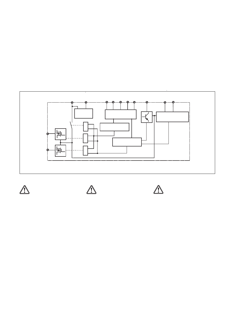
Innenschaltbild
Internal wiring diagram
Schéma interne
• Querschlusserkennung wird durch
Taktung der Eingangskreise ermöglicht.
Diese Betriebsart wird beim Start auto-
matisch erkannt.
• Anlauftest verhindert einen automati-
schen Wiederanlauf nach Spannungs-
ausfall und -wiederkehr. Das Gerät prüft,
ob nach Anlegen der Versorgungsspan-
nung geschlossene Schutztüren geöffnet
und wieder geschlossen werden.
• Kontaktvervielfachung und -verstärkung
durch Anschluss eines Kontaktblockes
(z. B. PZE X4.1P) oder von externen
Schützen.
Sicherheitsschaltgerät montieren
Achtung! Durch elektrostatische
Entladung können Bauteile des
Sicherheitssystems beschädigt
werden. Sorgen Sie für Entladung,
bevor Sie das Sicherheitssystem
berühren, z. B. durch Berühren einer
geerdeten, leitfähigen Fläche oder
durch Tragen eines geerdeten
Armbands.
• Montieren Sie das Sicherheitsschaltgerät
in einen Schaltschrank mit einer Schutzart
von mindestens IP54.
• Befestigen Sie das Gerät mit Hilfe des
Rastelements auf der Rückseite auf einer
Normschiene.
• Sichern Sie das Gerät auf einer senk-
rechten Normschiene (35 mm) durch ein
Halteelement (z. B. Endhalter oder
Endwinkel).
• Start-up test prevents an automatic
restart when power is restored following a
voltage loss. The unit checks whether
closed safety gates are opened and closed
again when operating voltage is applied.
• The number of safety contacts can be
increased by connecting a contact block
(e.g. PZE X4.1P) or external contactors.
Installing the relay
Caution! Electrostatic discharge can
damage components on the safety
system. Ensure against discharge
before touching the safety system,
e.g. by touching an earthed,
conductive surface or by wearing an
earthed armband.
• Install the safety relay in a control cabinet
with a minimum protection type of IP54.
• Use the notch on the rear of the unit to
attach it to a DIN-rail.
• Attach the unit securely to a vertical DIN
rail (35 mm) using a fixture such as a
retaining bracket or end angle.
• La détection des court-circuits est rendue
possible par test impulsionnel des circuits
d’entrée. Ce mode de fonctionnement est
identifié automatiquement lors du
réarmement.
• Le test des conditions initiales prévient
le redémarrage automatique après
coupure/rétablissement de la tension
d'alimentation. L’appareil vérifie si les
protecteurs mobiles qui étaient fermées
après application de la tension
d’alimentation ont été ouverts puis
refermés.
• Augmentation du nombre de contacts
ou de leur pouvoir de coupure par le
raccordement d’un bloc de contacts
d'extension (par exemple PZE X4.1P) ou
de contacteurs externes.
Installer le bloc logique de sécurité
Attention ! Une décharge électro-
statique peut endommager les
éléments du système de sécurité.
Veillez à vous décharger avant de
toucher le système de sécurité, par
ex. en touchant une surface
conductrice mise à la terre ou en
portant un bracelet de mise à la
terre.
• Installez le bloc logique de sécurité dans
une armoire d’indice de protection au
moins IP54.
• Montez l'appareil sur un rail DIN à l'aide du
système de fixation situé au dos du relais.
• Fixer l’appareil sur un rail DIN vertical (35
mm) avec un élément de maintien comme
par ex. un support ou une équerre
terminale.