Wiring, Preparing for operation – Pilz PZE X4VP 0,5/24VDC 4n/o fix User Manual
Page 7
PZE X4VP
Operating Manual PZE X4VP
1003202EN08
7
}
If more than 2 units are installed next to each other in the control cabinet, leave a dis
tance of at least 6 mm between the units.
Wiring
Please note:
}
Information given in the "
}
Outputs 1718, 2728, 3738 and 4748 are delayon deenergisation safety contacts.
}
To prevent contact welding, a fuse should be connected before the output contacts (see
Technical details).
}
Calculation of the max. cable runs l
max
in the input circuit:
R
lmax
R
l
/ km
I
max
=
R
lmax
= max. overall cable resistance (see Technical details)
R
l
/ km = cable resistance/km
}
Use copper wire that can withstand 60/75 °C.
}
Sufficient fuse protection must be provided on all output contacts with capacitive and in
ductive loads.
}
Do not switch low currents using contacts that have been used previously with high cur
rents.
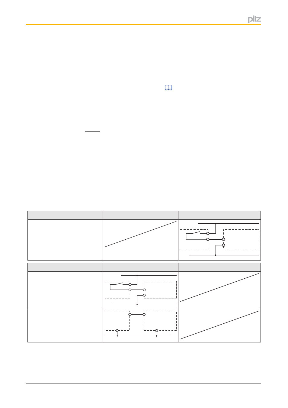
Preparing for operation
Supply voltage
AC
DC
A1
A2
PZE
24 V DC
0 V
Input circuit
Singlechannel
Dualchannel
Base unit:
Safety relay PNOZ X
Driven via safety contacts
A1
A2
PZE
24 V DC
0 V
Base unit:
Safety relay PNOZmulti
Driven via semiconductor outputs
(24 VDC)
A1
PZE
A2
0 V
O1
L-