Block diagram/terminal configuration, Function description, Installation – Pilz PZE X4VP 0,5/24VDC 4n/o fix User Manual
Page 6
PZE X4VP
Operating Manual PZE X4VP
1003202EN08
6
}
Earth fault in the feedback loop:
Detected, depending on the base unit that is used.
}
Earth fault in the input circuit:
The output relays deenergise and the safety contacts open.
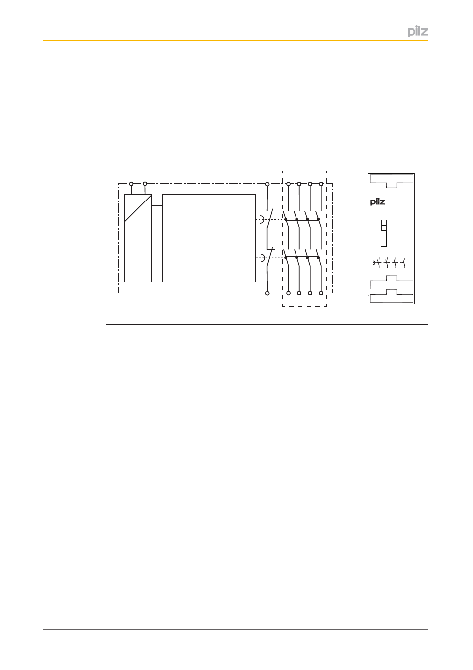
Block diagram/terminal configuration
*
=
=
Power
K1
Input
A1
A2
17 27 37
Y1
18 28 38
Y2
47
48
K2
CH.2
CH.1
PNOZ X4VP 3s
P1
17
A1
Y1 Y2 47
28
18
A2
P1
P2
27
18
17
38
37
27
28
37
47
48
38
48
PZE X4VP
*Insulation between the nonmarked area and the relay contacts: Basic insulation (over
voltage category III), Protective separation (overvoltage category II)
Function description
The contact expansion module is an addon device with delayon deenergisation, and it is
used to expand a safety circuit. The contact expansion module is driven by a base unit (e.
g. emergency stop relay).
}
Functional procedure after closing the safety contacts of the base unit:
–
The supply voltage is present at the input (A1) of the contact expansion module.
–
Close the safety contacts 1718, 2728, 3738 and 4748.
–
The LEDs "CH. 1" and "CH. 2" are lit.
}
Functional procedure after opening the safety contacts of the base unit:
–
There is not supply voltage at input (A1) of the contact expansion module.
–
Safety contacts 1718, 2728, 3738 and 4748 open after the delay time.
–
The LEDs "CH. 1" and "CH. 2" go out.
Installation
}
The unit should be installed in a control cabinet with a protection type of at least IP54.
}
Use the notch on the rear of the unit to attach it to a DIN rail.
}
Ensure the unit is mounted securely on a vertical DIN rail (35 mm) by using a fixing ele
ment (e.g. retaining bracket or an end angle).