Block diagram/terminal configuration, Function description, Pze x4 – Pilz PZE X4 24VDC 4n/o User Manual
Page 6
PZE X4
Operating Manual PZE X4
1003199EN08
6
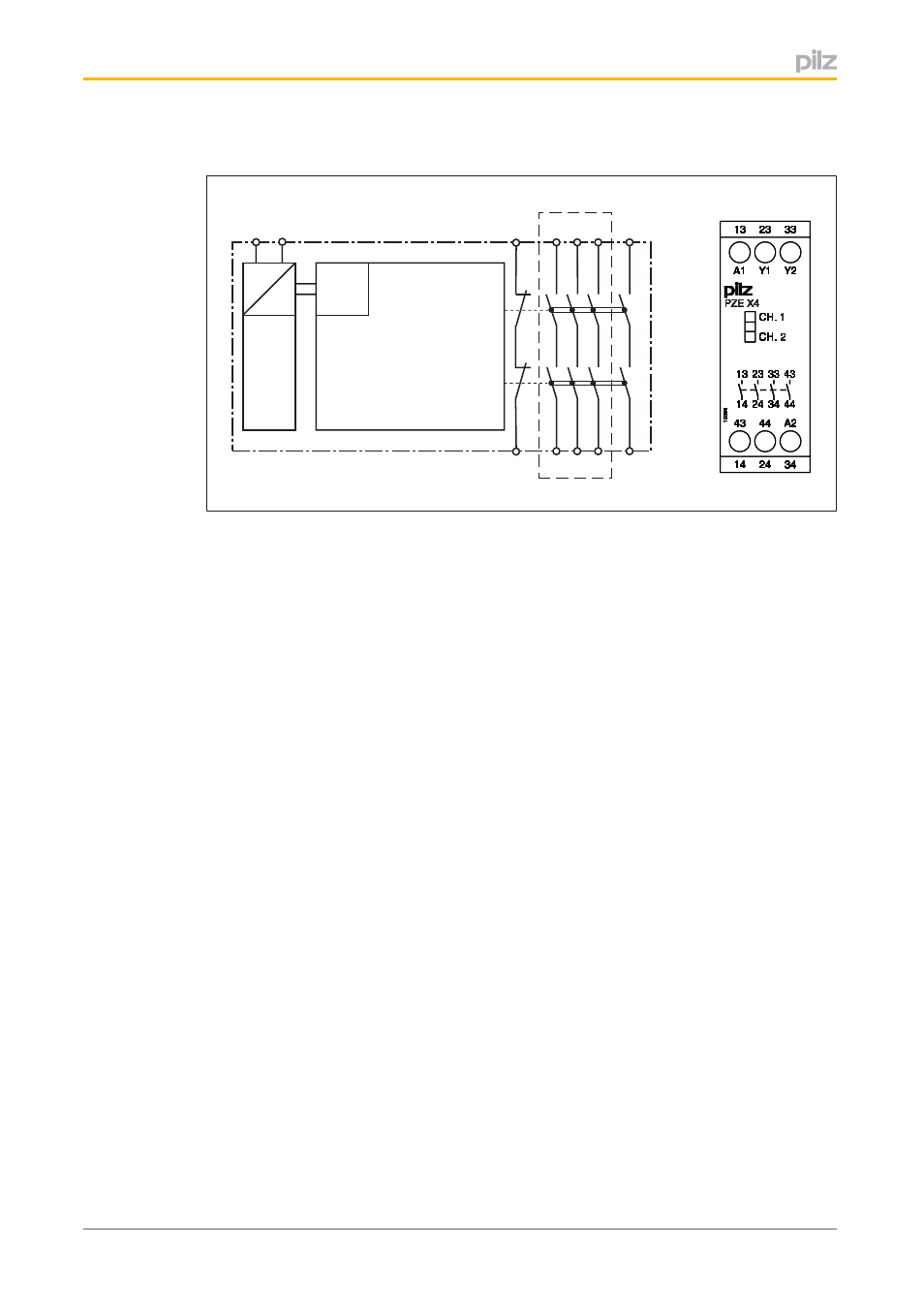
Block diagram/terminal configuration
=
=
Power
K1
Input
A1
A2
13 23 33
Y1
14 24 34
Y2
43
44
K2
*
1
9
3
9
6
CH.
CH.
A2
43
44
34
24
14
Y2
A1
Y1
33
13
23
44
34
14 24
33
13 23
43
1
9
3
9
6
1
9
3
9
6
1
9
3
9
6
1
9
3
9
6
1
9
3
9
6
1
9
3
9
6
1
9
3
9
6
CH
CH
CH
CH
CH
CH
CH
.
..
.
.
.
.
CH
CH
CH
CH
CH
CH
CH
.
..
.
.
.
.
A2
A2
A2
A2
A2
A2
A2
43
43
43
43
43
43
43
44
44
44
44
44
44
44
34
34
34
34
34
34
34
24
24
24
24
24
24
24
14
14
14
14
14
14
14
Y2
Y2
Y2
Y2
Y2
Y2
Y2
A1
A1
A1
A1
A1
A1
A1
Y1
Y1
Y1
Y1
Y1
Y1
Y1
33
33
33
33
33
33
33
13
13
13
13
13
13
13
23
23
23
23
23
23
23
44
44
44
44
44
44
44
34
34
34
34
34
34
34
14
14
14
14
14
14
14
24
24
24
24
24
24
24
33
33
33
33
33
33
33
13
13
13
13
13
13
13
23
23
23
23
23
23
23
43
43
43
43
43
43
43
PZE X4
PZE X4
PZE X4
PZE X4
PZE X4
PZE X4
PZE X4
1
1
1
1
1
1
1
2
2
2
2
2
2
2
* Protective separation in accordance with EN 609471, 6 kV
Function description
The contact expansion module is an addon device without delayon deenergisation, and it
is used to expand a safety circuit. The contact expansion module is driven by a base unit
(e. g. emergency stop relay).
}
Functional procedure after closing the safety contacts of the base unit:
–
The supply voltage is present at the input (A1) of the contact expansion module.
–
Close the safety contacts 1314, 2324, 3334 and 4344.
–
The LEDs "CH. 1" and "CH. 2" are lit.
}
Functional procedure after opening the safety contacts of the base unit:
–
There is not supply voltage at input (A1) of the contact expansion module.
–
Open the safety contacts 1314, 2324, 3334 and 4344.
–
The LEDs "CH. 1" and "CH. 2" go out.