Anwendung, Application, Utilisation – Pilz PNOZ XV1P 3/24VDC 2n/o 1n/o t User Manual
Page 4
- 4 -
Wird der Eingangskreis geöffnet, öffnen die
Sicherheitskontakte 13-14/23-24 und die
Statusanzeige "CH.1/2" erlischt. Nach Ablauf
der Verzögerungszeit öffnet der Sicherheits-
kontakt 37-38 und die Statusanzeige "CH.1/
2(t)" erlischt.
Wieder aktivieren:
• Schließen Sie den Eingangskreis oder
betätigen Sie den Starttaster erst
wieder nach Ablauf der Verzögerungs-
zeit + Toleranz.
• Eingangskreis schließen.
• Bei manuellem Start mit Überwachung
Taster zwischen S33 und S34 betätigen.
Die Statusanzeigen leuchten wieder, die
Sicherheitskontakte sind geschlossen.
Anwendung
If the input circuit is opened, the safety
contacts 13-14/23-24 open and the status
indicator "CH.1/2" extinguishs. After the
delay-on-de-energisation period the saftey
contact 37-38 opens and the status indicator
"CH.1/2(t)" extinguishs.
Reactivation:
• Close the input circuit, or operate the
start button only when the delay time +
tolerance have elapsed.
• Close the input circuit.
• For manual reset with monitoring, press
the button and release between S33-S34.
The status indicators light up again, the
safety contacts are closed.
Si le circuit d’entrée est ouvert, les contacts
de sécurité 13-14/23-24 retombent et le LED
"CH.1/2" s'éteigne. À la fin de la
temporisation, les contact de sécurité 37-38
retombe et le LED "CH.1/2(t)" s’éteigne.
Remise en route :
• Fermez le canal d’entrée ou n’appuyez
sur le poussoir de réarmement qu’après
l’écoulement du temps de
temporisation + tolérance.
• fermer le circuit d’entrée
• en cas de surveillance du circuit de
réarmement, appuyer le poussoir de
validation S33-S34.
Les affichages d'état s'allument à nouveau.
Les contacts de sécurité sont fermées.
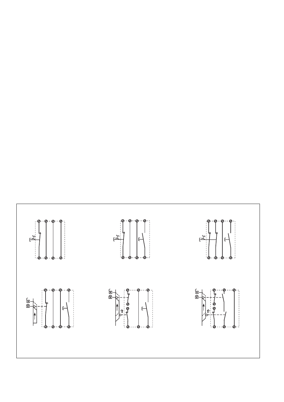
In Fig. 2 ... Fig. 10 sind Anschlussbeispiele für
Not-Halt-Beschaltung mit automatischem und
überwachtem Start, Schutztürsteuerungen
sowie Kontaktvervielfachung durch externe
Schütze.
Bitte beachten Sie:
• Fig. 2 und 7: keine Verbindung S33-S34.
Beachten Sie: Das Gerät startet bei
Spannungsausfall und -wiederkehr automa-
tisch. Verhindern Sie einen unerwarteten
Wiederanlauf durch externe Schaltungs-
maßnahmen.
• Fig. 3, 4, 5, 6, 8:
keine Verbindung S11-S14
• Fig. 7: Automatischer Start bei Schutztür-
steuerung: Das Gerät ist bei geöffneter
Schutztür über den Startkreis S11-S14
startbereit. Nach Schließen der Eingangs-
kreise S11-S12, S21-S22 und S12-S32
werden die Sicherheitskontakte geschlos-
sen.
Application
In Fig. 2 ... Fig. 10 are connection examples
for Emergency Stop wiring with automatic
and monitored reset. Safety gate controls as
well as contact expansion via external
contactors.
• Fig. 2 and 7: S33-S34 not connected.
Please note: the device starts automatically
after loss of power. You should prevent an
unintended start-up by using external
circuitry measures.
• Fig 3, 4, 5, 6, 8: S11-S14 not connected
• Fig. 7: Automatic reset with safety gate
control: with the safety gate open the unit
is ready for operation via reset circuit S11-
S14. After closing the safety input circuit
S11-S12, S21, S22 and S12-S32 the
safety contacts will close.
Utilisation
Les figures 2 à 10 représentent les différents
câblages possibles du PNOZ XV1P à savoir :
poussoir AU avec réarmement automatique
ou auto-côntrolé, interrupteurs de position et
augmentation du nombre des contacts de
sécurité par contacteurs externes.
• Fig. 2 et 7: pas de câblage sur S33-S34.
L’appareil se réarme automatiquement après
une coupure et une remise sous tension.
Evitez tout risque de redémarrage par un
câblage externe approprié.
• Fig. 3, 4, 5, 6, 8:
pas de câblage sur S11-S14
• Fig. 7: Réarmement automatique en cas
de surveillance protecteur: lorsque le
protecteur est ouvert, le circuit S11-S14 se
ferme et le relais est prêt à fonctionner.
Dès la fermeture des canaux d'entrée S11-
S12, S21-S22 et S12-S32, les contacts de
sortie du relais se ferment.
S21
S11 S33
S22
S34
S12
S1
S3
S12
S32
S11 S12
S11
S12
S14
S32
S21
S22
S1
S11 S12
S33
S12
S34
S32
S21
S22
S1
S3
S32 S34
S33
S12
S11
S22
S12
S21
S1
S3
S12 S34
S33
S11
S21
S32
S22
S12
S1
S2
S3
S12
S14
S11
S11
S21
S32
S22
S1
S2
S12
Fig. 7: Schutztürsteuerung zweikanalig,
automatischer Start/Two channel safety gate
control, automatic reset/Surveillance de
protecteur, commande par 2 canaux,
validation automatique
Fig. 6: Schutztürsteuerung zweikanalig,
überwachter Start/Two-channel safety gate
control, monitored reset/Surveillance de
protecteur, commande par 2 canaux,
surveillance du poussoir de validation
Fig. 5: Schutztürsteuerung einkanalig,
überwachter Start/Single-channel safety gate
control, monitored reset/Surveillance de
protecteur, commande par 1 canal,
surveillance du poussoir de validation
Fig. 4: Eingangskreis zweikanalig, überwach-
ter Start/Two-channel input circuit, monitored
reset/Commande par 2 canaux, surveillance
du poussoir de validation
Fig. 3: Eingangskreis einkanalig, überwach-
ter Start/Single-channel input circuit,
monitored reset/Commande par 1 canal,
surveillance du poussoir de validation
Fig. 2: Eingangskreis einkanalig, automat.
Start/Single-channel input circuit, automatic
reset/Commande par 1 canal, validation
automatique