Function description, Funktionsbeschreibung, Description du fonctionnement – Pilz PNOZ XV1P 3/24VDC 2n/o 1n/o t User Manual
Page 2
- 2 -
Function Description
The relay PNOZ XV1P provides a safety-
oriented interruption of a safety circuit. When
the operating voltage is supplied the LED
"PWR" is illuminated. The unit is ready for
operation, when the reset circuit S11-S14 is
closed or a reset contact at S33-S34 was
opened and closed again.
• Input Circuit closed (e.g. the Emergency
Stop button is not pressed):
Relays K1, K2, K3 and K4 energise and
retain themselves. The status indicators
for "CH.1/2" and "CH.1/2(t)" illuminate.
The safety contacts (13-14/23-24/37-38)
are closed.
• Input Circuit is opened (e.g. Emergency
Stop is pressed)
Relays K1 and K2 de-energise. The status
indicator for "CH.1/2" goes out. The safety
contacts 13-14/23-24 will be opened
(redundant). Following the delay-on de-
energisation period, relays K3 and K4 de-
energise. The safety contact 37-38 opens
and the LED "CH.1/2(t)" extinguishs.
The unit may only be reset once the delay-
on-de-energisation period has lapsed.
Funktionsbeschreibung
Das Schaltgerät PNOZ XV1P dient dem
sicherheitsgerichteten Unterbrechen eines
Sicherheitsstromkreises. Nach Anlegen der
Versorgungsspannung leuchtet die LED
"PWR". Das Gerät ist betriebsbereit, wenn
der Startkreis S11-S14 geschlossen ist oder
ein Startkontakt an S33-S34 geöffnet und
wieder geschlossen wurde.
• Eingangskreis geschlossen (z. B. Not-Halt-
Taster nicht betätigt):
Relais K1, K2, K3 und K4 gehen in Wirk-
stellung und halten sich selbst. Die
Statusanzeigen für "CH.1/2" und "CH.1/
2(t)" leuchten. Die Sicherheitskontakte 13-
14/23-24/37-38 sind geschlossen.
• Eingangskreis wird geöffnet (z. B. Not-
Halt-Taster betätigt):
Relais K1 und K2 fallen in die Ruhe-
stellung zurück. Die Statusanzeige für
"CH.1/2" erlischt. Die Sicherheitskontakte
13-14 und 23-24 werden redundant
geöffnet. Nach Ablauf der eingestellten
Verzögerungszeit fallen die Relais K3 und
K4 zurück. Der Sicherheitskontakt 37-38
öffnet und die LED "CH.1/2(t)" erlischt.
Bevor das Gerät erneut gestartet werden
kann, muss die Verzögerungszeit abgelau-
fen sein.
Description du fonctionnement
Le relais PNOZ XV1P assure de façon sure,
l’ouverture d’un circuit de sécurité. A la mise
sous tension du relais (A1-A2), la LED
"PWR" s'allume. Le relais est activé si le
circuit de réarmement S11-S14 est fermé ou
si le contact de réarmement sur S33-S34 a
été ouvert puis refermé.
• Circuits d'entrée fermés (poussoir AU non
actionné) :
Les relais K1, K2, K3 et K4 passent en
position travail et s'auto-maintiennent. Les
LEDs "CH.1/2" et "CH.1/2(t)" s'allument.
Les contacts de sécurité (13-14/23-24/37-
38) sont fermés.
• Circuits d'entrée ouverts (poussoir AU
actionné) :
Les relais K1 et K2 retombent. Le LED
"CH.1/2" s'éteingne. Les contacts de
sécurité 13-14/23-24 s'ouvrent. Au bout de
la temporisation affichée, les relais K3 et
K4 retombent. Les contact de sécurité 37-
38 s'ouvre et le LED "CH.1/2/t)" s'éteigne.
La temporisation doit être écoulée avant de
pouvoir réarmer à nouveau le relais.
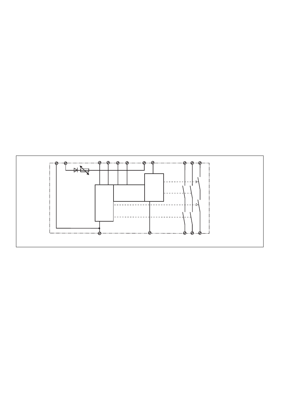
Fig. 1: Innenschaltbild/Internal Wiring Diagram/Schéma de principe
A1
A2
S14
S12
S21
S34
S11
S22
13
37
14
38
K1
K2
23
24
CH1
CH2
Start
Unit
S33
+
-
K4
K3
S32
Betriebsarten
• Einkanaliger Betrieb:
Eingangsbeschaltung nach EN 60204-1
(VDE 0113 Teil 1) und IEC 60204-1 keine
Redundanz im Eingangskreis, Erdschlüsse
im Tasterkreis werden erkannt.
• Zweikanaliger Betrieb: Redundanter Ein-
gangskreis, Erdschlüsse im Tasterkreis
und Querschlüsse zwischen den Taster-
kontakten werden erkannt.
• Automatischer Start: Gerät ist aktiv, sobald
Eingangskreis geschlossen ist.
• Manueller Start mit Überwachung: Gerät
ist nur aktiv, wenn vor dem Schließen des
Eingangskreises der Startkreis geöffnet
wird und der Startkreis nach dem Schlie-
ßen des Eingangskreises und nach Ablauf
der Wartezeit (s. techn. Daten) geschlos-
sen wird. Dadurch ist eine automatische
Aktivierung und Überbrückung des
Starttasters ausgeschlossen.
• Kontaktvervielfachung und -verstärkung
durch Anschluss von externen Schützen.
Operating Modes
• Single-channel operation: Input wiring
according to EN 60204-1 (VDE 0113 Teil 1)
and IEC 60204-1 no redundancy in the input
circuit, earth faults are detected in the
emergency stop circuit.
• Two-channel operation: Redundancy in the
input circuit, earth faults in the Emergency
Stop circuit and shorts across the
emergency stop push button are also
detected.
• Automatic reset: Unit is active as soon as
the input circuit is closed.
• Manual reset with monitoring: Unit will only
be active if the reset circuit is opened
before the input circuit closes, and the
reset circuit is closed after the input circuit
has closed and the waiting time has
elapsed (see technical data). This
eliminates the possibility of the reset
button being overridden, triggering
automatic activation.
• Increase in the number of available
contacts by connection of external
contactors/relays.
Modes de fonctionnement
• Commande par 1 canal : conforme aux
prescriptions de la EN 60204-1 (VDE 0113
Teil 1) et IEC 60204-1 pas de redondance
dans le circuit d’entrée, la mise à la terre
du circuit d’entrée est détectée
• Commande par 2 canaux: circuit d’entrée
redondant, la mise à la terre et les courts-
circuits entre les contacts sont détectés.
• Réarmement automatique : le relais est
activé dès la fermeture des canaux
d’entrée.
• Réarmement manuel auto-contrôlé:
L'appareil est uniquement actif lorsque le
circuit de réarmement est ouvert avant
fermeture des circuits d'entrées et que le
circuit de réarmement est fermé après
fermeture des circuits d'entrées et
écoulement du temps d'attente (voir les
charactéristiques techniques). Cette
mesure permet d'éviter toute activation
automatique et toute inhibition du poussoir
de réarmement.
• Augmentation du nombre de contacts ou
du pouvoir de coupure par l’utilisation de
contacteurs externes.