Description du fonctionnement, Function description, Funktionsbeschreibung – Pilz PNOZ XV2.1 30/24-240VACDC 2n/o 2n/o t User Manual
Page 2: Betriebsarten, Operating modes, Modes de fonctionnement
- 2 -
Description du fonctionnement
Le relais PNOZ XV2.1 assure de façon sure,
l’ouverture d’un circuit de sécurité. A la mise
sous tension du relais (A1-A2), la LED
"Power" s'allume. Le relais est activé si le
circuit de réarmement S13-S14 est fermé ou
si le contact de réarmement sur S33-S34 a
été ouvert puis refermé. La LED "START"
s'allume.
• Circuits d'entrée fermés (poussoir AU non
actionné) :
Les relais K1, K2, K3 et K4 passent en
position travail et s'auto-maintiennent. Les
LEDs "CH.1", " CH.2" et "CH.1(t)",
"CH.2(t)" s'allument. Les contacts de
sécurité (13-14/23-24/37-38/47-48) sont
fermés.
• Circuits d'entrée ouverts (poussoir AU
actionné) :
Les relais K1 et K2 retombent. Les LEDs
"CH.1" et "CH.2" s'éteingnent. Les
contacts de sécurité 13-14/23-24
s'ouvrent. Au bout de la temporisation
affichée, les relais K3 et K4 retombent. Les
contacts de sécurité 37-38/47-48 s'ouvrent
et les LEDs "CH.1(t)" et "CH.2(t)"
s'éteignent.
Les canaux d'entrée doivent être refermés et
la temporisation écoulée avant de pouvoir
réarmer à nouveau le relais (ex. boucle de
retour).
Arrêt de la temporisation
Un action sur un BP rellé au bornes Y39-Y40
(contact à ouverture) permet d'interrompre
prématurément la temporisation et d'ouvrir
instantanément les contacts de sortie 37-38
et 47-48.
Function Description
The relay PNOZ XV2.1 provides a safety-
oriented interruption of a safety circuit. When
the operating voltage is supplied the LED
"Power" is illuminated. The unit is ready for
operation, when the reset circuit S13-S14 is
closed or a reset contact at S33-S34 was
opened and closed again. The status
indicator "START" is illuminated.
• Input Circuit closed (e.g. the Emergency
Stop button is not pressed):
Relays K1, K2, K3 and K4 energise and
retain themselves. The status indicators
for "CH.1", "CH.2" and "CH.1(t)", CH.2(t)"
illuminate. The safety contacts (13-14/23-
24/37-38/47-48) are closed.
• Input Circuit is opened (e.g. Emergency
Stop is pressed)
Relays K1 and K2 de-energise. The status
indicators for "CH.1" and "CH.2" go out.
The safety contacts 13-14/23-24 will be
opened (redundant). Following the delay-
on de-energisation period, relays K3 and
K4 de-energise. The safety contacts 37-38
and 47-48 opens and the LED "CH.1(t)"
and "CH.2(t)" extinguish.
The unit may only be reset once the delay-
on-de-energisation period has lapsed and all
E-Stop and safety contacts (e. g. feedback
control loop) are closed.
Interruption of Delay-on De-energisation:
By opening the contact Y39-Y40 ie pressing
a button connected the set delay-on de-
energisation will be interrupted and the safety
contacts 37-38 and 47-48 will open
immediately.
Funktionsbeschreibung
Das Schaltgerät PNOZ XV2.1 dient dem
sicherheitsgerichteten Unterbrechen eines
Sicherheitsstromkreises. Nach Anlegen der
Versorgungsspannung leuchtet die LED
"Power". Das Gerät ist betriebsbereit, wenn
der Startkreis S13-S14 geschlossen ist oder
ein Startkontakt an S33-S34 geöffnet und
wieder geschlossen wurde. Die Statusan-
zeige "START" leuchtet.
• Eingangskreis geschlossen (z. B. Not-Halt-
Taster nicht betätigt):
Relais K1, K2, K3 und K4 gehen in
Wirkstellung und halten sich selbst. Die
Statusanzeigen für "CH.1", "CH.2" und
"CH.1(t), "CH.2(t)" leuchten. Die
Sicherheitskontakte 13-14/23-24/37-38/47-
48 sind geschlossen.
• Eingangskreis wird geöffnet (z. B. Not-
Halt-Taster betätigt):
Relais K1 und K2 fallen in die Ruhe-
stellung zurück. Die Statusanzeige für
"CH.1" und "CH.2" erlischt. Die Sicher-
heitskontakte 13-14 und 23-24 werden
redundant geöffnet. Nach Ablauf der
eingestellten Verzögerungszeit fallen die
Relais K3 und K4 zurück. Die Sicherheits-
kontakte 37-38 und 47-48 öffnen und die
LED "CH.1(t)" und "CH.2(t)" erlöschen.
Bevor das Gerät erneut gestartet werden
kann, muss die Verzögerungszeit abgelaufen
und alle Not-Halt- und Sicherheitskontakte
(z. B. Rückführkreis) müssen wieder
geschlossen sein.
Verzögerungszeit unterbrechen:
Durch Betätigen eines Reset-Tasters (Y39-
Y40) wird die eingestellte Verzögerungszeit
unterbrochen und die Sicherheitskontakte 37-
38 und 47-48 sofort geöffnet.
* Isolation zum nicht markierten Bereich und der
Relaiskontakte zueinander: Basisisolierung
(Überspannungskategorie III), sichere Trennung
(Überspannungskategorie II)
Betriebsarten
• Einkanaliger Betrieb: Eingangsbeschaltung
nach VDE 0113 Teil 1 und EN 60204-1,
keine Redundanz im Eingangskreis,
Erdschlüsse im Tasterkreis werden
erkannt.
• Zweikanaliger Betrieb: Redundanter Ein-
gangskreis, Erdschlüsse im Tasterkreis
und Querschlüsse zwischen den Taster-
kontakten werden erkannt.
• Automatischer Start: Gerät ist aktiv, sobald
Eingangskreis geschlossen ist.
* Insulation between the non-marked area
and the relay contacts: Basic insulation
(overvoltage category III), safe separation
(overvoltage category II)
Operating Modes
• Single-channel operation: Input wiring
according to VDE 0113 part 1 and
EN 60204-1, no redundancy in the input
circuit, earth faults are detected in the
emergency stop circuit.
• Two-channel operation: Redundancy in
the input circuit, earth faults in the
Emergency Stop circuit and shorts across
the emergency stop push button are also
detected.
* Isolation de la partie non sélectionnée par
rapport aux contacts relais : isolation basique
(catégorie de surtensions III), isolation
galvanique (catégorie de surtensions II)
Modes de fonctionnement
• Commande par 1 canal : conforme aux
prescriptions de la EN 60 204/1, pas de
redondance dans le circuit d’entrée, la
mise à la terre du circuit d’entrée est
détectée
• Commande par 2 canaux: circuit d’entrée
redondant, la mise à la terre et les courts-
circuits entre les contacts sont détectés.
• Réarmement automatique : le relais est
activé dès la fermeture des canaux
d’entrée.
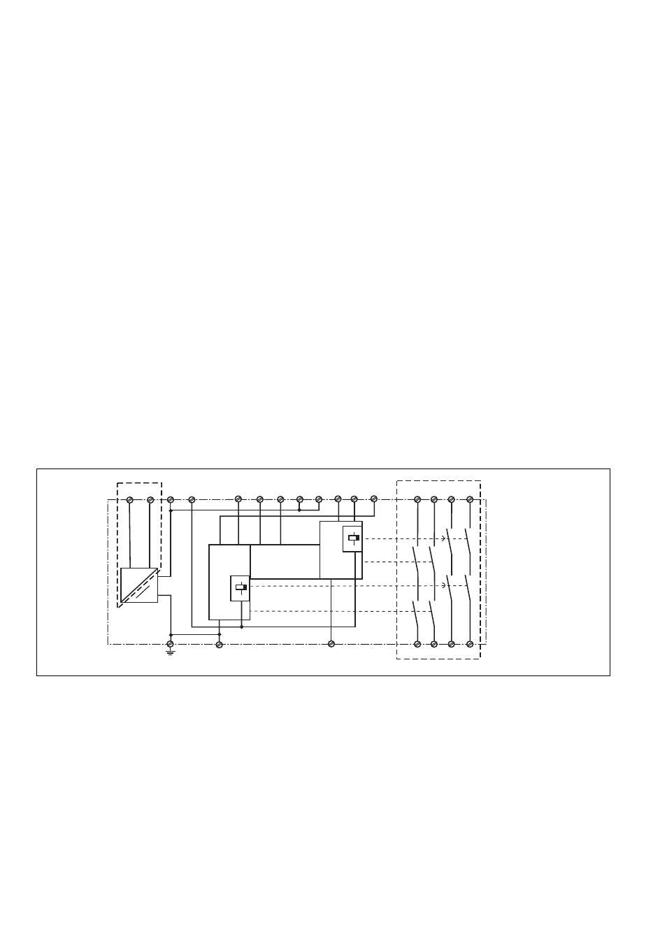
Fig. 1: Innenschaltbild/Internal Wiring Diagram/Schéma de principe
S13
S14
S12
S21
S34
47
48
S11
S22
S32
S31
13
37
14
38
K1
K2
23
24
CH1
CH2
Start
Unit
S33
Y39
Y40
K4
K3
____
A1
A2
~~
__
__
+
*
*
- PNOZ XV2.1 3/24-240VACDC 2n/o 2n/o t PNOZ XV2.1 0.5/24-240VACDC 2n/o 2n/o fix PNOZ XV2.1 300/24-240VACDC 2n/o 2n/o t PNOZ XV2.1P 30/24-240VACDC 2n/o 2n/o t PNOZ XV2.1P 3/24-240VACDC 2n/o 2n/o t PNOZ XV2.1P 0.5/24-240VACDC 2n/o 2n/o fi PNOZ XV2.1P 300/24-240VACDC 2n/o 2n/o t PNOZ XV2.1P C 30/24-240VACDC 2n/o 2n/o t PNOZ XV2.1P C 3/24-240VACDC 2n/o 2n/o t PNOZ XV2.1P C 300/24-240VACDC 2n/o 2n/o PNOZ XV2 30/24VDC 2n/o 2n/o t PNOZ XV2 3/24VDC 2n/o 2n/o t PNOZ XV2 0.5/24VDC 2n/o 2n/o fix PNOZ XV2 3/24VDC 2n/o 2n/o fix PNOZ XV2 10/24VDC 2n/o 2n/o fix PNOZ XV2 300/24VDC 2n/o 2n/o t