Pilz PZA 300/24VAC 1n/o 2n/c User Manual
Page 2
- 2 -
Funktionsbeschreibung
Das Zeitrelais dient der Entsperrung einer
Verriegelung mit Verzögerung. Der Zeitwert
der Verzögerung ist in 12 Stufen einstellbar.
Voraussetzung: Rückführkreis geschlossen.
Das Zeitrelais wird durch Unterbrechen bzw.
Anlegen der Versorgungsspannung akti-
viert. Im Ruhezustand ist die Versor-
gungsspannung zwischen A1 und A2 unter-
brochen. Der Sicherheitskontakt 17-18 ist
offen, die Hilfskontakte (25-26 und 35-36)
geschlossen. Durch Anlegen der
Versorgungsspannung beginnt der Zeit-
ablauf. Nach Ablauf des eingestellten Zeit-
werts schließt der Sicherheitskontakt und
die Hilfskontakte öffnen.
Function Description
The Timer Relay provides a time-delayed
release of a locking device. The time delay
is selectable in 12 steps.
System Requirements: Feedback Control
Loop closed.
The timer relay reacts to the operating
voltage being supplied or interrupted. In
rest condition, the operating voltage
between A1 and A2 is interrupted. The
safety contact 17-18 is open, the auxiliary
contacts (25-26 and 35-36) closed. When
the operating voltage is supplied, the time
delay period commences. When the set time
period has elapsed, the safety contact
closes and the auxiliary contacts open.
Description du fonctionnement
Le relais permet le pilotage temporisé d'un
système d'interverrouillage. La valeur de la
temporisation est réglable par un
commutateur 12 positions.
Préalable : la boucle de retour est fermée.
Le relais est activé par l'application de la
tension d'alimentation. En position repos, la
tension d'alimentation entre A1 et A2 est
inter-rompue. Le contact de sécurité 17-18
est ouvert, les contacts d'info (25-26 et
35-36) sont fermés. Dès que la tension
d'alimentation est appliquée, la
temporisation commence. Au bout de la
valeur affiché, le contact de sécurité se
ferme et les contacts d'info. s'ouvrent.
A1 (L+) A2 (L-)
Y1
Y2
18
26
36
K1
K2
K1
K2
Zeitkreis1/
timer 1/
Circuit tem-
porisation 1
Vergleicherstufe/
Comparator/
Etage comparateur
Vergleicherstufe/
Comparator/
Etage comparateur
K1
K2
K2
K1
K1
17
25
35
K2
Netzteil/
Power
supply/
Alimen-
tation
Power ON
Reset
Zeitkreis2/
timer 2/
Circuit tem-
porisation 2
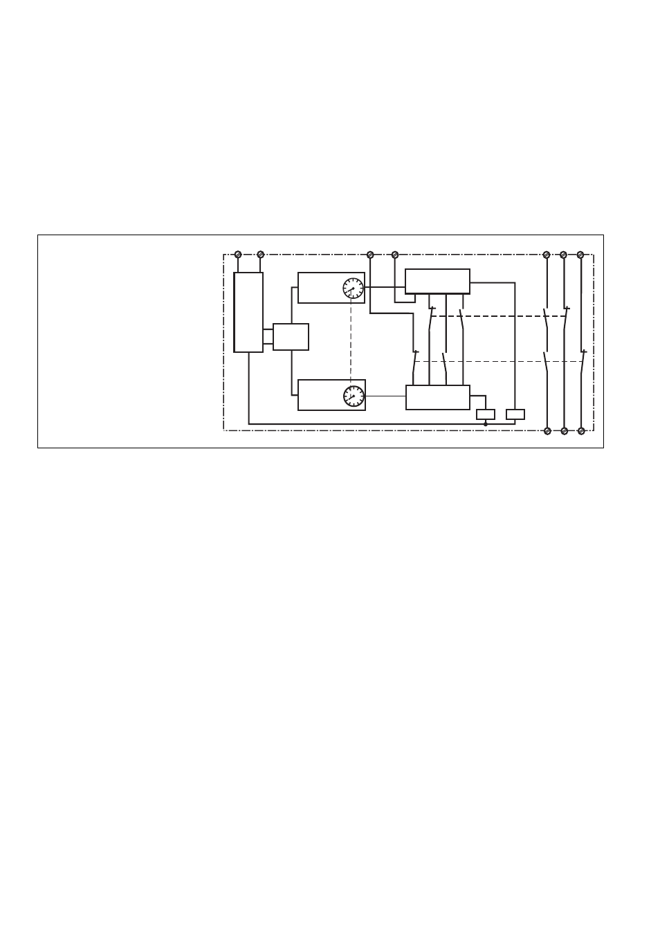
Schematisches Schaltbild/
Internal wiring diagram/
Schéma interne
Montage
Le relais doit être installé dans une armoire
ayant un indice de protection IP 54. Sa face
arrière permet un montage sur rail DIN.
Mise en oeuvre
Remarques préliminaires :
• Seul le contact 17-18 est un contact de
sécurité. Les contacts 25-26 et 35-36
sont des contacts d'information (par ex.
pour la signalisation).
• Protéger les contacts de sortie par des
fusibles (voir les caractéristiques
techniques) pour éviter leur soudage
• Utiliser uniquement des fils de câblage en
cuivre 60/75 °C.
• Respecter les données indiquées dans le
chapitre "Caractéristiques techniques".
Mise en oeuvre :
• Sélectionner sur le commutateur la
temporisation désirée à l'aide d'un
tournevis
• Fermer la boucle de retour :
pont entre Y1-Y2 ou câblage des
contacts externes.
• Amener la tension d'alimentation sur les
bornes A1(+) et A2 (-).
Montage
Das Sicherheitsschaltgerät muss in einen
Schaltschrank mit einer Schutzart von mind.
IP 54 eingebaut werden. Zur Befestigung
auf einer Normschiene hat das Gerät ein
Rastelement auf der Rückseite.
Inbetriebnahme
Beachten Sie bei der Inbetriebnahme:
• Nur der Ausgangskontakt 17-18 ist ein
Sicherheitskontakt. Die Ausgangs-
kontakte 25-26 und 35-36 sind Hilfs-
kontakte
(z. B. für Anzeige).
• Vor die Ausgangskontakte eine Siche-
rung (s. techn. Daten) schalten, um das
Verschweißen der Kontakte zu verhin-
dern.
• Leitungsmaterial aus Kupferdraht mit ei-
ner Temperaturbeständigkeit von
60/75 °C verwenden
• Angaben im Kapitel "Technische Daten"
unbedingt einhalten.
Ablauf:
• Markierung auf Drehschalter mit einem
Werkzeug (z. B. Schraubendreher) auf
gewünschten Zeitwert drehen.
• Rückführkreis schließen
Brücke an Y1-Y2 oder externe Schütze
anschließen.
• Eingangskreis (Versorgungsspannung)
an Klemmen A1 (+) und A2 (-) anschlie-
ßen.
Installation
The safety relay must be panel mounted
(min. IP 54). There is a notch on the rear of
the unit for DIN-Rail attachment.
Operation
Please note for operation:
• Only the output contact 17-18 is a safety
contact. The output contacts 25-26 and
35-36 are auxiliary contacts (e.g. for
monitoring).
• To prevent contact welding, a fuse
(see technical detail) must be
connected before the output contacts.
• Use 60/75 °C copper wire only.
• Important details in the section "Technical
Data" should be noted and adhered to.
To operate:
• Using a screwdriver, turn the rotary switch
to the required time delay setting
• Close the feedback control loop.
Bridge Y1-Y2 or connect external
contactors/relays.
• Connect the input circuit (operating
voltage) to terminals A1 (+) and A2 (-).
If the operating voltage is interrupted (rest