Setup instructions, Components, Connecting the power cables – UVP 81-0345-01 ChemiDoc-ItTS2 Imager User Manual
Page 9: Components connecting the power cables
GelDoc-It
TS2
and ChemiDoc-It
TS2
Imagers
9
Setup Instructions
Components
When unpacking the GelDoc-It
TS2
and ChemiDoc-It
TS2
, the following items will be included:
1. GelDoc-It
TS2
or ChemiDoc-It
TS2
system
2. Ethidium bromide (EtBr) emission filter
3. Transilluminator
4. Power cable
5. USB flash drive (8 GB minimum)
6. Keyboard and mouse
7. VisionWorksLS Software (if included; varies by country)
8. Supporting documentation
When unpacking and setting up the darkroom, two people are required to move the darkroom.
Place the darkroom on a flat surface which can provide adequate support for up to 100 pounds.
WARNING: Do not attempt to perform any setup procedures while the system is plugged in or powered on
unless otherwise instructed.
CAUTION: Do not install the system in areas with high moisture, dust or high temperatures. Keep the
equipment away from motors or any other large magnetic equipment. This system is designed for indoor use
only.
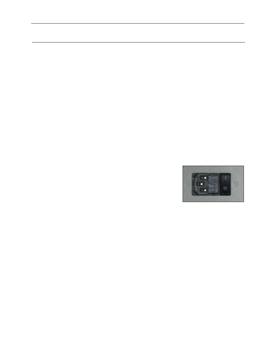
Connecting the Power Cables
1. Plug the main power cable into the back of the darkroom and the
other end into a surge-protected power outlet.
Note: It is recommended to leave the power switch on the back of
the system in the ON position except when the system will not be
used for an extended period of time (one day or longer).
Note: Do not position the system so that it is difficult to access the
power cable and operate the main power switch at the back of the unit.
2. Inside the darkroom, place the transilluminator on the roll-out tray. Connect the transilluminator to the
internal power jumper cable. Ensure that the green power switch on the front of the transilluminator unit
is in the ON position and that the desired wavelength or intensity is selected.
Note: For UV protection and to extend the life of the UV transilluminator, the system incorporates a
customizable transilluminator shutoff timer built into the software. For additional information, refer to
Touch Screen Interface in this manual.
3. If installing the LED White Light Plate, place the plate on top of the UV transilluminator and connect the
power cord coming from inside the darkroom to the back of the Plate.
4. If installing epi UV modules, place the modules in the brackets located at the top of the darkroom. Plug
the modules into the outlets provided inside the darkroom. Place the power switches located on the
modules in the ON position.