Module error definition table – Spectrum Controls 1769sc-IF8u User Manual
Page 71
Chapter 5: Diagnostics and Troubleshooting
61
Module Error
Definition Table
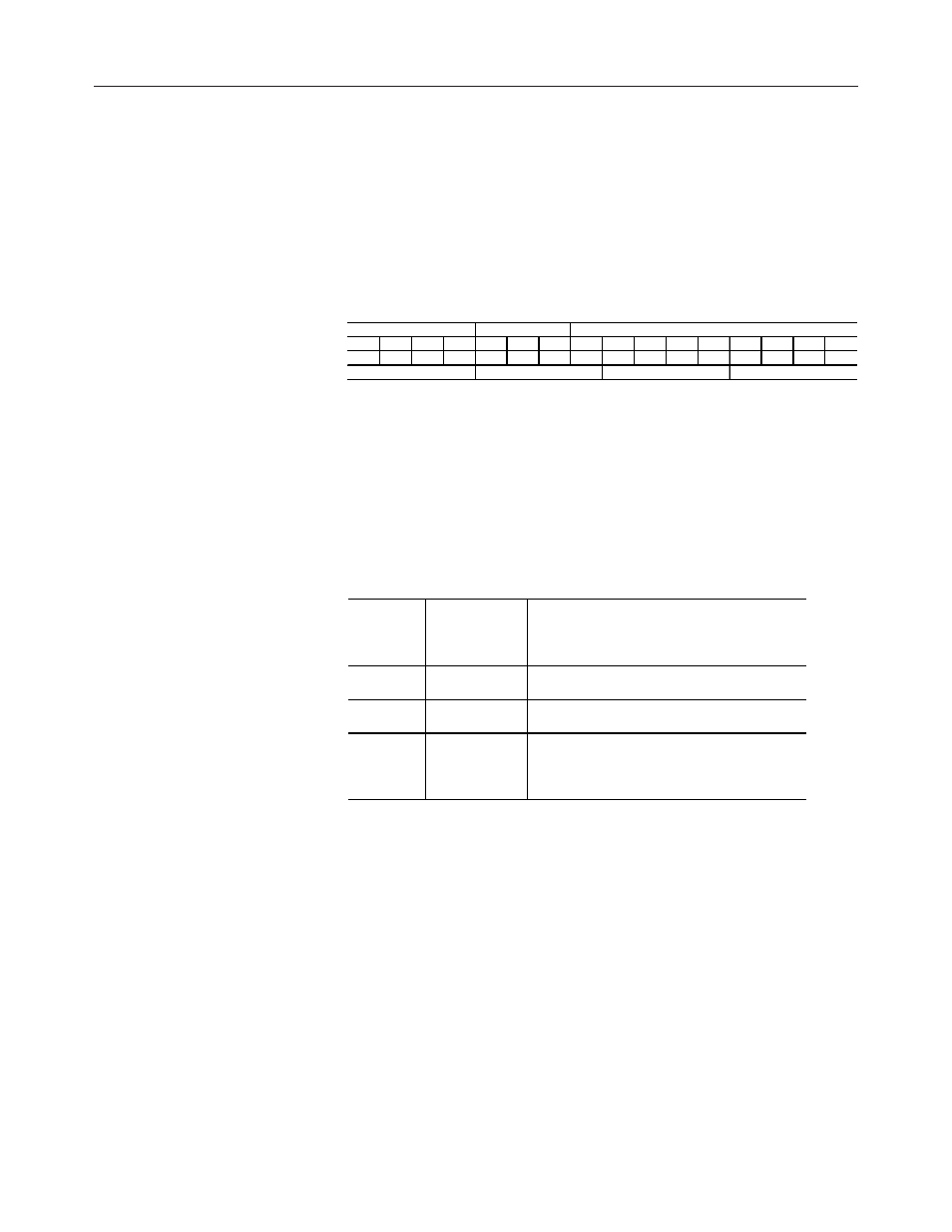
Analog module errors are expressed in two fields as four-digit Hex format
with the most significant digit as “don’t care” and irrelevant. The two
fields are “Module Error” and “Extended Error Information”. The
structure of the module error data is shown below.
Table 5.1 Module Error Table
15
14
13
12
11
10
9
8
7
6
5
4
3
2
1
0
0
0
0
0
0
0
0
0
0
0
0
0
0
0
0
0
"Don't Care" Bits
M odule Error
Extended Error Inform ation
Hex Digit 4
He x Digit 3
Hex Digit 2
Hex Digit 1
Module Error Field
The purpose of the module error field is to classify module errors into
three distinct groups, as described in the table below. The type of error
determines what kind of information exists in the extended error
information field. These types of module errors are typically reported in
the controller’s I/O status file. Refer to your controller manual for details.
Table 5.2 Module Error Types
Error Type
Module Error
Field Value Bits
11 through 9
(binary)
Description
No errors
000
No error is present. The extended error field holds no
additional information.
Hardw are
Errors
001
General and specific hardw are error codes are
specified in the extended error information field.
Configuration
Errors
010
Module-specific error codes are indicated in the
extended error field. These error codes correspond to
options that you can change directly. For example, the
input range or input filter selection.
Extended Error Information Field
Check the extended error information field when a non-zero value is
present in the module error field. Depending upon the value in the module