Spectrum Controls 1769sc-IF8u User Manual
Page 21
Chapter 2: Quick Start for Experienced Users
11
!
ATTENTION! Remove power before removing or inserting this
module. If you remove or insert a module with power applied, an electrical
arc may occur.
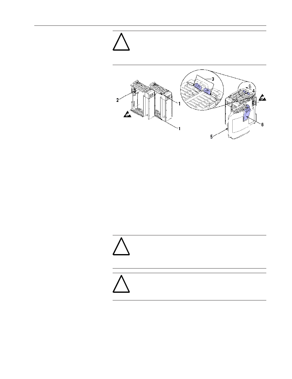
1. Check that the bus lever of the module to be installed is in the
unlocked (fully right) position.
2. Use the upper and lower tongue-and-groove slots (1) to secure the
modules together (or to a controller).
3. Move the module back along the tongue-and-groove slots until the bus
connectors (2) line up with each other.
4. Push the bus lever back slightly to clear the positioning tab (3). Use
your fingers or a small screwdriver.
5. To allow communication between the controller and module, move the
bus lever fully to the left (4) until it clicks. Ensure it is locked firmly in
place.
6. Attach an end cap terminator (5) to the last module in the system by
using the tongue-and-groove slots as before.
7. Lock the end cap bus terminator (6).
!
ATTENTION! When attaching I/O modules, it is very important that the
bus connectors are securely locked together to ensure proper electrical
connection.
!
IMPORTANT A 1769-ECR or 1769-ECL right or left end cap respectively
must be used to terminate the end of the 1769 communication bus.