Spectrum Controls 1769sc-IF8u User Manual
Page 57
Chapter 4: Module Data, Status, and Configuration
47
to reach 100% of its expected final value, given a full-scale step change in
the input signal. This means that if an input signal changes faster than the
channel step response, a portion of that signal will be attenuated by the
channel filter. The channel step response is calculated by a settling time of
3 x (1/filter frequency).
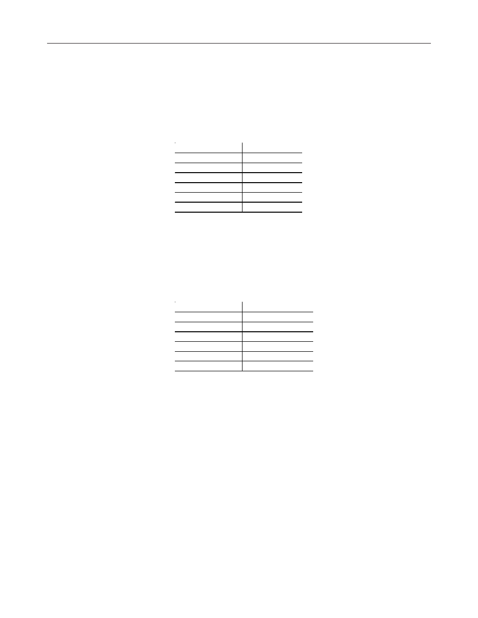
Table 4.4 Filter Frequency and Step Response
Filter Frequency Step Response
10 Hz
300 ms
50 Hz
60 ms
60 Hz
50 ms
250 Hz
12 ms
500 Hz
6 ms
1 KHz
3 ms
Channel Cut-Off Frequency
The filter cut-off frequency, -3 dB, is the point on the frequency response
curve where frequency components of the input signal are passed with 3
dB of attenuation. The following table shows cut-off frequencies for the
supported filters.
Table 4.5 Filter Frequency versus Channel Cut-off Frequency
Filter Frequency Cut-off Frequency
10 Hz
2.62 Hz
50 Hz
13.1 Hz
60 Hz
15.7 Hz
250 Hz
65.5 Hz
500 Hz
131 Hz
1 KHz
262 Hz
All input frequency components at or below the cut-off frequency are
passed by the digital filter with less than 3 dB of attenuation. All frequency
components above the cut-off frequency are increasingly attenuated as
shown in the graphs on the next page.