Accessing input, Input data file – Spectrum Controls 1769sc-IF8u User Manual
Page 44
34
Compact IO
™
Universal Input module
Accessing Input
Accessing Input
Accessing Input
Accessing Input
Accessing Input
Image File Data
Image File Data
Image File Data
Image File Data
Image File Data
The input image file represents data words and status words. Input words
0 through 7 hold the input data that represents the value of the analog
inputs for channels 0 through 7. These data words are valid only when the
channel is enabled and there are no errors. Input words 8, 9 and 10 hold
the status bits. To receive valid status information, the channel must be
enabled.
You can access the information in the input image file using the
programming software configuration screen. For information on
configuring the module in a MicroLogix 1500 system using RSLogix 500,
see Appendix E; for CompactLogix using RSLogix 5000, see Appendix F.
Input Data File
Input Data File
Input Data File
Input Data File
Input Data File
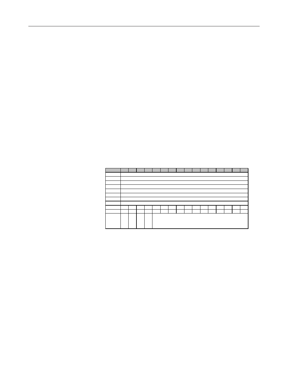
The input data table allows you to access module read data for use in the
control program, via word and bit access. The data table structure is
shown in the table below.
Table 4.1 Input Data Table
Word/Bit¹ 15
14
13
12
11
10
9
8
7
6
5
4
3
2
1
0
0
1
2
3
4
5
6
7
8
OC7 OC6 OC5 OC4 OC3 OC2 OC1 OC0 S7
S6
S5
S4
S3
S2
S1
S0
9
U7
O7
U6
O6
U5
O5
U4
O4
U3
O3
U2
O2
U1
O1
U0
O0
10
S8
O8
U8 OC8
(1) Changing bit values is not supported by all controllers. Refer to your controller manual for details.
CJC Value
(Degrees C X 10 [0..850
10
])
(Degrees F X 10 [320..1850
10
])
Analog Input Data Channel 4
Analog Input Data Channel 5
Analog Input Data Channel 6
Analog Input Data Channel 7
Analog Input Data Channel 0
Analog Input Data Channel 1
Analog Input Data Channel 2
Analog Input Data Channel 3
Input Data Values
Data words 0 through 7 correspond to channels 0 through 7 and contain
the converted analog input data from the input device. The most significant
bit, bit 15, is the sign bit (SGN).
General Status Bits (S0 to S7) Bits S0 through S7 of word 8 contain the
general status information for channels 0 through 7, respectively. Bit S8 of
word 10 contains general status information for the CJC sensor. If set (1),
this bit indicates an error (over- or under-range, open-circuit or input data
not valid condition) associated with that channel or CJC. The data not
valid condition is described below.