Spectrum Controls 1756sc-IF8u User Manual
Page 30
18
ControlLogix
™
Universal Analog Input Module
Wiring RTD or
Resistance Sensors
to the IF8u Module
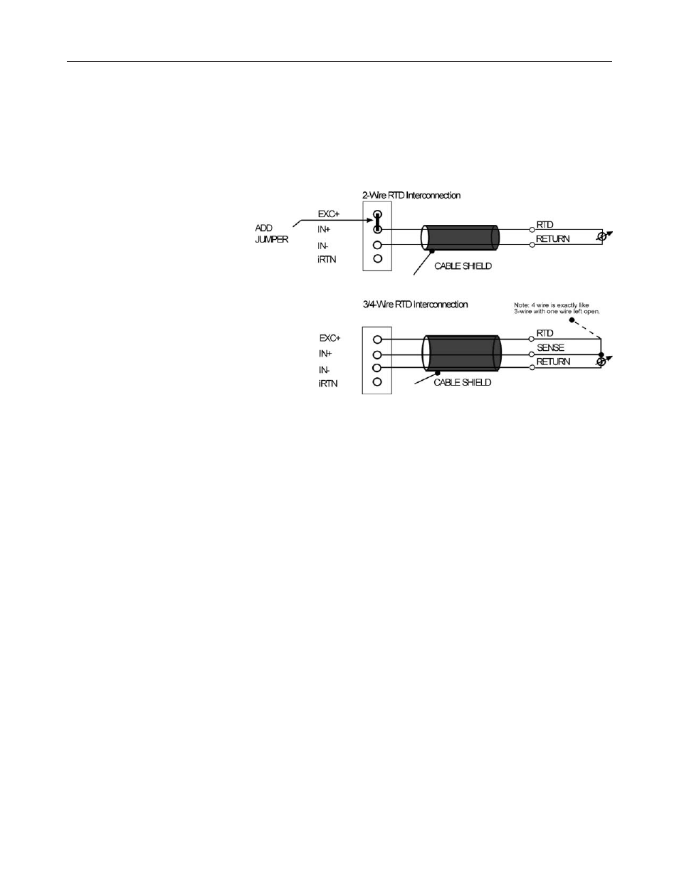
The IF8u module supports two, three, and four wire RTDs or resistance
inputs connected individually to the module as shown in the figure below.
These are:
* 2-wire RTDs, which are composed of 2 RTD lead wires (EXC+ and
IN- with a jumper between EXC+ and IN+)
* 3-wire RTDs, which are composed of a 2 Signal and 1 RTD return lead
wires (EXC+ and IN+ with a the return RTD lead to IN-)
* 4-wire RTDs, which are composed of 2 Signal and 2 RTD return lead
wires (EXC+ and IN+ with a the return RTD lead to IN-) The fourth
lead is not used so wiring is identical to 3 wires RTDs.
* 2- wire Resistance, which is composed of 2 leads (EXC+ and IN- with
a jumper between EXC+ and IN+)
* 3- wire Resistance, which is composed of 3 leads (EXC+ IN+ and
IN-) and the resistance lies between IN+ and IN-
In any RTD sensing system, it is important that the lead and sense wire
resistances are matched as much as possible. The lead lengths, and their
resulting impedances, must be matched and kept small to eliminate the
introduction of connectivity errors. The 3/4-wire RTDs are the most
accurate, with 2-wire RTDs being the most inaccurate. In 2-wire the lead
resistance adds error to the resulting degree reading. With a 1.008mA
current source, 1
Ω of lead resistance adds 1.008µV, or 2.82°C error, with
the 100
Ω 385 alpha type. To gain an understanding of how lead
resistance affects RTD readings, the µV/C for each RTD type is listed
below.