SOR Single Point Ultrasonic Level Switch User Manual
Page 9
Form 829 (08.13) ©SOR Inc.
9/16
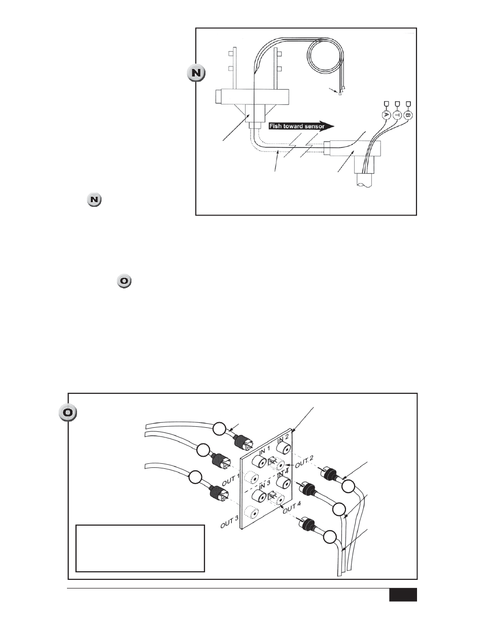
Coax Connections Inside Sensor Base
Inside the sensor base, a remote interconnect board rests in a plastic holder. Slide the
interconnect board up. Attach the sensor coax connectors to the interconnect board as
follows (See
):
Connect cable A to IN 1. [Sensor cavity A (upper)
receiver crystal]
Connect cable B to IN 3. [Sensor cavity B (lower) receiver crystal]
Connect cable T to IN 2. (Transmitter crystals)
Attach the extension cables to the interconnect board as follows:
Connect cable A to OUT 1.
Connect cable B to OUT 3.
Connect cable T to OUT 2.
Avoid mismatched connections which could render the unit inoperative.
Protect
factory
installed
plugs
Sensor base
Conduit must meet
Class I Group C & D;
Class II Groups E ,F & G:
Division 1 & 2
Electronics
Housing
Fishing the Sensor Extension
Cables Three sensor extension
cables are supplied. Both ends
of the cables are terminated
and labeled at the factory.
Use care to avoid damaging
the factory installed coax
connectors while fishing
the sensor extension cables
through the conduit. Pull
cables from the sensor base
so that the free ends follow
the fish through the conduit.
(See
) Leave enough cable
in the electronics housing to
make PC board connections.
Connect extension
lead T to OUT 2
Remote Interconnect Board
located inside sensor base
Connect T
lead to IN 2
Connect A
lead to IN 1
Connect B
lead to IN 3
Connect extension lead B to OUT 3
Connect extension lead A to OUT 1
OUT connections are located on the
opposite side of the board from the
IN connections. Do not use position
4 to connect wires.
B
A
T
B
A
T