SOR Single Point Ultrasonic Level Switch User Manual
Page 8
8/16
Form 829 (08.13) ©SOR Inc.
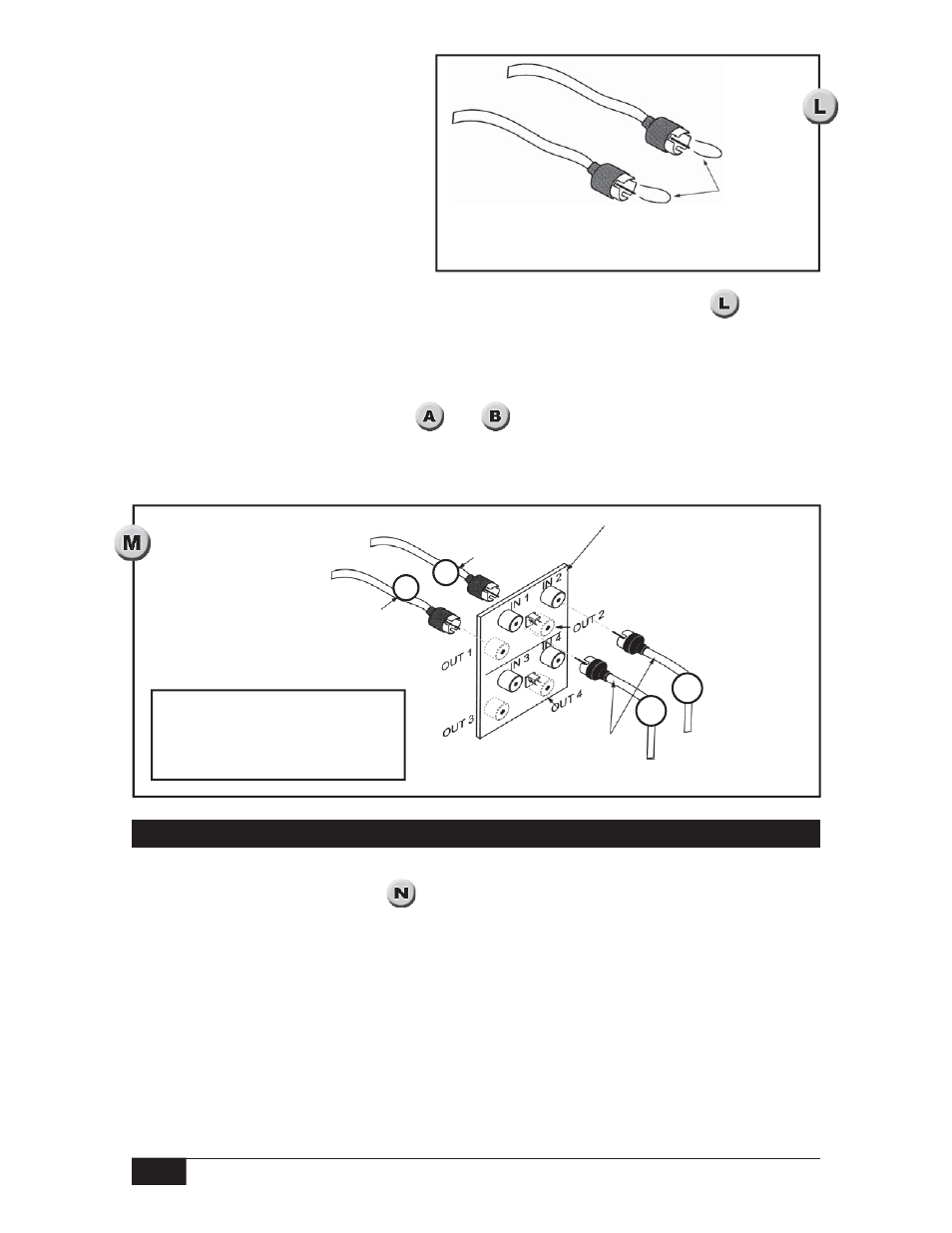
Discharge the Sensor
Temperature changes which occur
during shipment may result in a
small electrical charge inside the
sensor crystals. This charge is
harmless to humans, but may result
in damage to the electronics if the
sensor is plugged in before it is
discharged. To discharge the sensor,
touch a wire to each sensor
Short each
center conductor to
the shell to discharge
sensor crystals.
connector so that the center conductor and outside shell make contact. (See
)
Plug in Connections Inside Electronics Housing
Plug sensor extension cables onto the PC board as follows:
Connect cable A to J1.
Connect cable T to J2. (See
and
)
Power to the electronics must be disconnected before removing the cover of the sensor
base in a hazardous area.
Connect extension
lead T to OUT 2
Remote Interconnect Board
located inside sensor base
Connect sensor
leads to IN 1 and IN 2
Connect extension lead A to OUT 1
OUT connections are located on the
opposite side of the board from the
IN connections. Do not use positions
3 and 4 to connect wires.
A
T
A
T
One Point Remote Cable Connection - Models 711R1 and 721R2 Only
Install conduit between the sensor base and the electronics housing to provide a raceway
for sensor extension cables. (See
) The sensor base and the electronics housing are
suitable for use in Class I Groups C & D; Class II Groups E, F & G; Divisions 1 & 2
hazardous locations. All conduit and fittings used for the installation must equal or
exceed this rating to maintain the explosion proof integrity of the assembly.
Ensure that wiring conforms to all applicable local and national electrical codes and install
unit(s) according to relevant national and local safety codes.