SOR Single Point Ultrasonic Level Switch User Manual
Page 7
Form 829 (08.13) ©SOR Inc.
7/16
One Point Remote Cable Connection - Models 711R1 and 721R2 Only
Install conduit between the sensor base and the electronics housing to provide a raceway
for sensor extension cables. (See
) The sensor base and the electronics housing are
suitable for use in Class I Groups C & D; Class II Groups E, F & G; Divisions 1 & 2 hazard-
ous locations. All conduit and fittings used for the installation must equal or exceed this
rating to maintain the explosion proof integrity of the assembly.
Ensure that wiring conforms to all applicable local and national electrical codes and install
unit(s) according to relevant national and local safety codes.
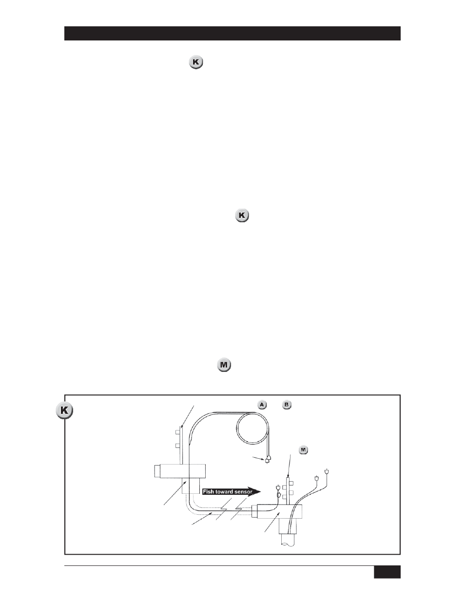
Fishing the Sensor Extension Cables
Two sensor extension cables are supplied. Both ends of the cables are terminated and
labeled at the factory.
Use care to avoid damaging the factory installed coax connectors while fishing the sensor
extension cables through the conduit. Pull cables from the sensor base so that the free
ends follow the fish through the conduit. (See
)
Leave enough cable in the electronics housing to make PC board connections.
Sensor Coax Connections Inside Sensor Base
Inside the sensor base, the remote interconnect board rests in a plastic holder. Slide the
interconnect board up.
Attach the extension cables to the interconnect board as follows:
Connect the long sensor cable (A) to IN 1.
Connect the short sensor cable (T) to IN 2.
Attach the extension cables to the interconnect board as follows:
Connect cable A to OUT 1.
Connect cable T to OUT 2. (See
)
Control Board See
and
Protect
factory
installed
plugs
Remote Interconnected Board
See
Sensor Base
Conduit must meet
Class I Groups C & D: Class II Groups
E, F & G Divisions 1 & 2
Electronics Housing