SOR Single Point Ultrasonic Level Switch User Manual
Page 10
10/16
Form 829 (08.13) ©SOR Inc.
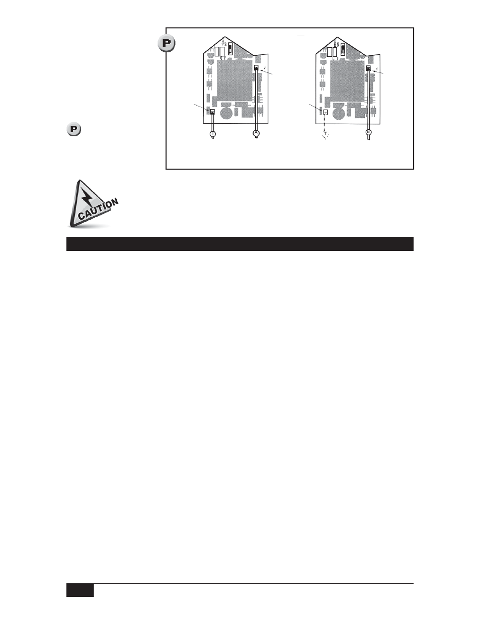
Plug in Connections
Inside Electronics
Housing
Discharge the sensor
per instructions on
page 8. Attach the PC
board connectors
according to Figure
. Note that cable T
can be connected to J2
on either the upper or
the lower PC Board.
Electrical power must be disconnected from explosion proof models before
the cover is removed. Failure to do so could result in severe personal injury
or substantial property damage.
J 2
Plug in
sensor
lead T
J 1
Plug in
sensor
lead A
PC Board
Labeled
UPPER
J 2
Alternate
Connection
for sensor
lead T
PC Board
Labeled
LOWER
J 1
Plug in
sensor
lead B
Time Delay Adjustments — Models 721 and 722 only
On Delay Timer Adjustment
On delay is an integral timer that starts when process liquid is detected in the sensor cavity.
Two point sensors have an On Delay timer for each sensor cavity. If the liquid level falls
before the On timer completes its cycle, the timer resets to zero and waits for the sensor
cavity to fill again. When the On timer completes its cycle, the liquid level relay changes
state to indicate liquid level is above the sensor.
Fully clockwise — 0-second delay
Fully counterclockwise — approximately 30-second delay
Off Delay Timer Adjustment
Off delay is an integral timer which starts when the liquid level falls. Two point sensors
have an Off Delay Timer for each sensor cavity. If the sensor cavity is refilled before the
Off timer completes its cycle, the timer resets to zero and waits for the sensor cavity to be
emptied again. When the Off timer completes its cycle, the liquid level relay changes state
to indicate liquid level is below the sensor.
Fully clockwise — 0-second delay
Fully counterclockwise — approximately 30-second delay