SOR Single Point Ultrasonic Level Switch User Manual
Page 3
Form 829 (08.13) ©SOR Inc.
3/16
Sensor Installation
Notch-Type Sensor (Series 37
- N)
Series 370 Ultrasonic Level Sensors can be mounted by inserting the sensor through a
fitting in a vessel, or the sensor may be suspended over an open sump or basin.
Tank or Vessel
Make sure that the sensor can be fully inserted and tightened without interference from
obstructions inside the tank or vessel. (See
)
Apply suitable sealant to the process connection to prevent process leakage.
Do not use the sensor base as a handle to tighten the process connection.
One Point Horizontal Sensor Mounting (Series 371 Notch-Type)
When tightened securely, the sensor cavity must face sideways for optimum drainage when
process liquid level drops below the sensor cavity.
An alignment mark X stamped on a wrench flat (or on the dry face of a flange below the
housing) shows sensor cavity orientation. (See
(
and
y
)
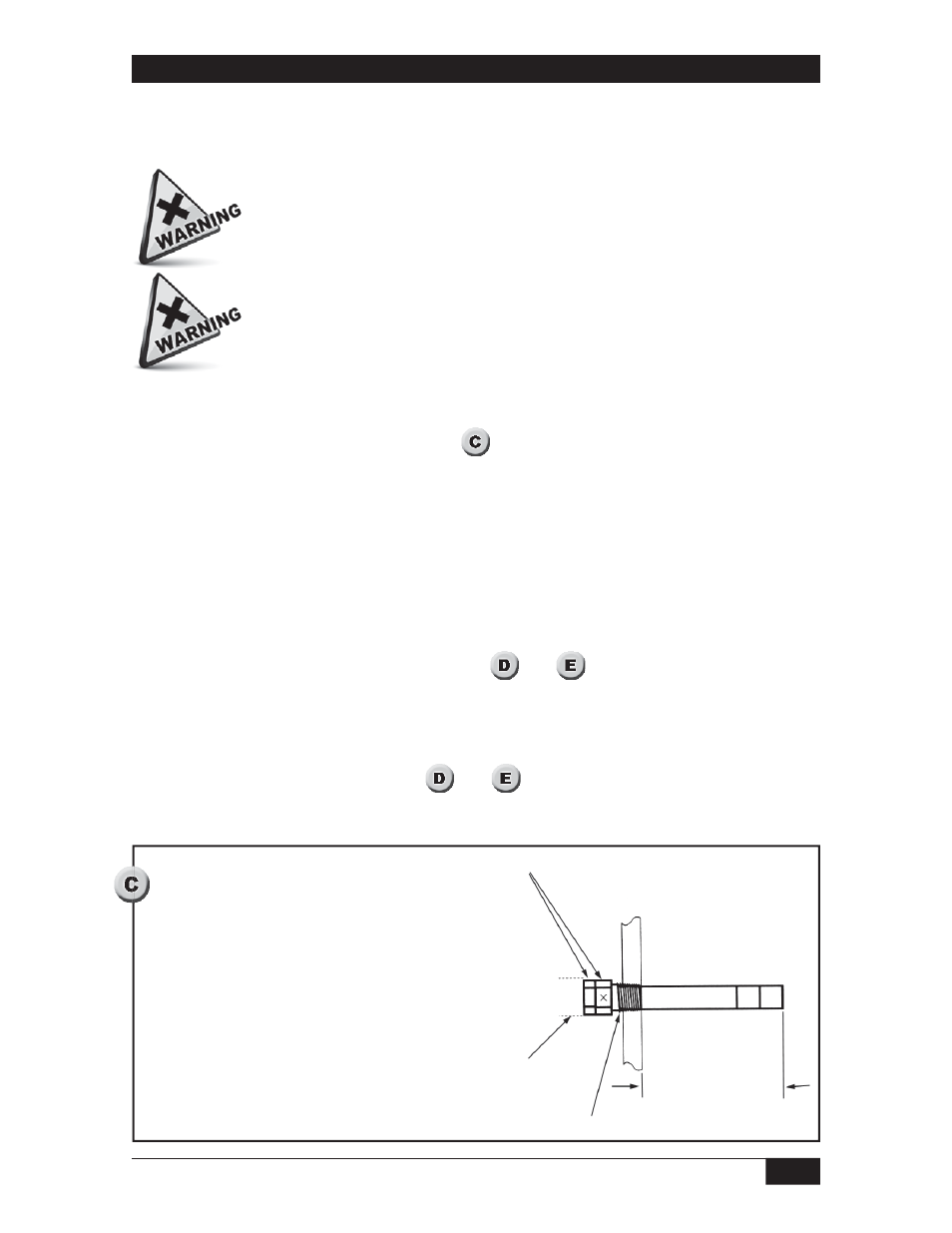
Notch-Type Sensors — Optimum drainage occurs when the X mark is located at 3 or 9 o’clock.
The sensor must project through a tank fitting so that the sensor cavity is at least 1”
beyond the inner wall of the tank. (See
and
)
DO NOT weld any part of this instrument.
Irreparable damage may be done to Tefl on sensors by turning Metal hex
and Tefl on hex separately. Always rotate Metal hex and Tefl on hex
simultaneously. Do not apply more than 10 in. lbs. of torque to either hex
during installation!
Tefl on Notch Sensor
(Metal sensor may vary)
Always turn Teflon hex & Metal hex together
when installing sensor into process.
Sensor Base Hub
No Obstructions
Apply thread sealant