SOR Single Point Ultrasonic Level Switch User Manual
Page 5
Form 829 (08.13) ©SOR Inc.
5/16
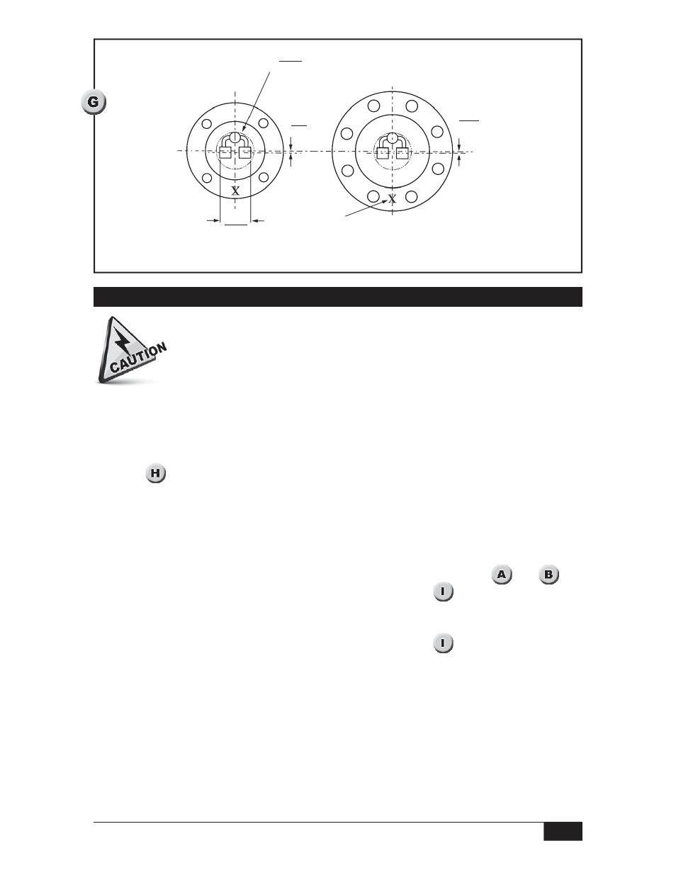
5.9
0.23
5.9
0.23
C
of flange
Bottom View
Viscous
Sensor
with
8-Hole
Flange
Alignment
mark (other side)
position at 6 o’clock (typ.)
Bottom View
Viscous
Sensor
with
4-Hole
Flange
62.1
2.44
(typ.)
Viscous Sensor
Cavity Orientation
ø 76.2 minimum
3.00 opening required (typ.)
L
Electrical Connection
Electrical power must be disconnected from explosion proof models before
the cover is removed. Failure to do so could result in severe personal injury
or substantial property damage.
Ensure that wiring conforms to all applicable local and national electrical codes and install
unit(s) according to relevant national and local safety codes.
A nine-position terminal strip provides connections for DPDT Liquid Level Relay Contacts,
Line Power and Ground. Terminal positions are labeled on the green insulator card as
shown in
.
Two point sensors have twin PC boards marked “Upper” or “Lower” for their matching
sensor cavities.
A. Liquid Level Relay Contact Terminals Before making connections to the Liquid Level
Relay Contact Terminals on the nine-position terminal strip, determine the fail safe
mode best suited for the application. Locate fail safe slide switch. (See
and
)
Refer to the continuity chart for the selected fail safe mode (
) when making
connections to the Liquid Level Relay Contact Terminal positions. When the unit is
used as an FM approved Low Water Level Limit Switch, the Fail safe Slide Switch
must be set to the HI position as shown in the upper half of
.
B. Line Power Terminals Terminals are provided for incoming power leads on the nine-
position PC board terminal strip. Supply voltage for each PC board is printed on the
green insulator card. Make sure that the available line voltage matches the device’s
power supply.
C. Ground Terminals The housing and the PC Board must be connected to ground.
Ground (earth) screws are provided on the nine-position PC board terminal strip and on
the housing floor. If extra clearance is required for connection to the ground screw on
the housing floor, the PC board can be removed and reinstalled according to PC Board
Field Replacement on page 11.