Nine-position liquid level relay terminal strip – SOR Single Point Ultrasonic Level Switch User Manual
Page 6
6/16
Form 829 (08.13) ©SOR Inc.
Sensor Monitor Connection - Models 721 and 722 only
B
Nine-Position Liquid Level Relay Terminal Strip
A
NC1
C1
NO1
NO2
C2
NC2
L1 N GND
NC1
C1
NO1
NO2
C2
NC2
+ - GND
NC1
C1
NO1
NO2
C2
NC2
L1 L2 GND
24VDC
120 VAC
240VAC
C
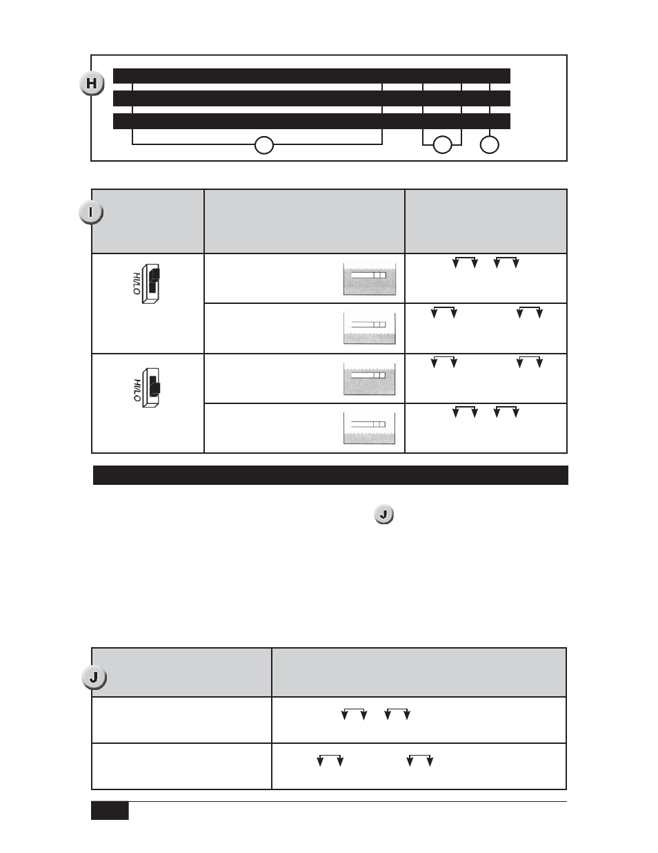
Any loss of the physical or electrical ultrasonic sensor integrity causes instantaneous
de-energizing of the DPDT sensor monitor relay. (See
) Two point sensors have one
sensor monitor relay for each sensor cavity.
A six-position terminal strip provides connections for each set of DPDT sensor monitor
relay contacts. Terminal positions are labeled on the green insulator card(s).
The sensor monitor is continuously on duty whenever the instrument is powered. It does
not require external initiation and it is not initiated at programmed intervals. If the sensor
monitor indicates a fault, see Troubleshooting on page 14.
Fail-safe Mode
Switch Position
Sensor Condition
Liquid Level Relay
Contact A
Continuity Chart
Relay energized
on high level
Liquid above sensor
NC1 C1 NO1 NO2 C2 NC2
Relay Energized
Liquid below sensor
NC1 C1 NO1 NO2 C2 NC2
Relay De-engergized
Relay energized on
low level
Liquid above sensor
NC1 C1 NO1 NO2 C2 NC2
Relay De-energized
Liquid below sensor
NC1 C1 NO1 NO2 C2 NC2
Relay Energized
Relay Continuity Chart
Sensor Status
Sensor Monitor Relay Contact
Continuity Chart
Functioning
NC1 C1 NO1 NO2 C2 NC2 Relay Energized
Sensor/Electronics Malfunction
Loss of Power Supply
NC1 C1 NO1 NO2 C2 NC2 Relay De-energized