SOR Single Point Ultrasonic Level Switch User Manual
Page 4
4/16
Form 829 (08.13) ©SOR Inc.
Sensor Installation
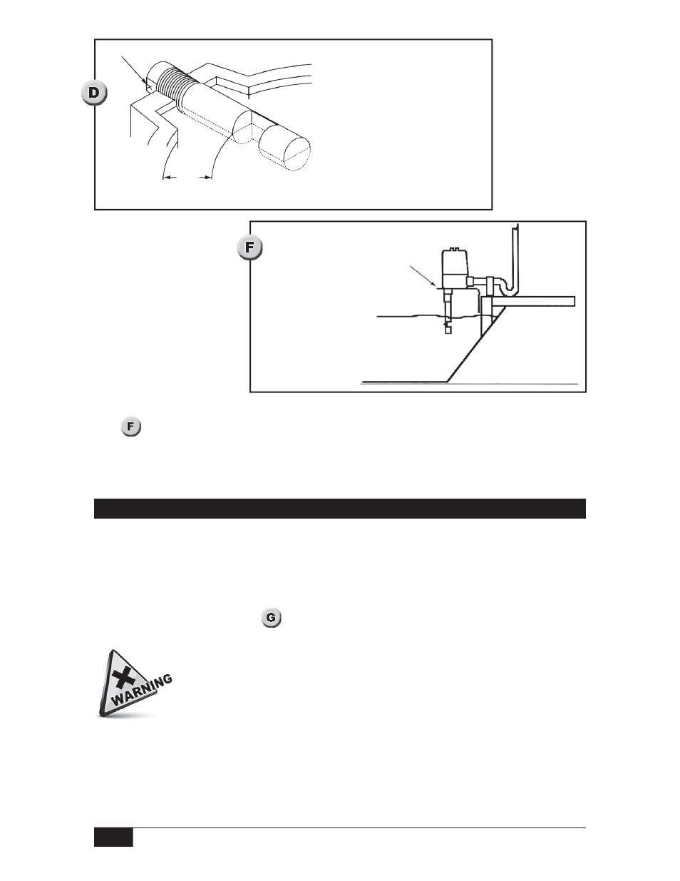
Notch-Type Sensor Mounting
Alignment mark shown at 3 o’clock
Alternate position: 9 o’clock
1
inch minimum
Open Sump or Basin
Do not suspend the unit
by rigid conduit installed
in the electrical hub. When
installing the unit over an
open sump or basin, use a
suitable bracket to support
the instrument.
Locally Supplied Bracket
Open Sump or Basin
Viscous Sensor (Series 371-V)
Vertical or horizontal (flange only) mounting is supported for the viscous sensor. A 3”
(76.2mm) diameter minimum opening is required for insertion.
An alignment mark X stamped on the dry face of the flange below the housing shows
sensor cavity orientation. (See
) Optimum drainage occurs when the X mark is located
at 6 o’clock.
Take care during installation to prevent damage to the sensor end. Slight bending of the
sensor may result in loss of sensitivity due to misalignment of the ultrasonic crystals.
DO NOT weld any part of this instrument.
NOTE: The instrument must be positioned so that overfl ow does not fl ood electrical housing
(see
)