Optical mark recognition (omr) • 5 – Pitney Bowes DI600 Inserting System User Manual
Page 71
Optical Mark Recognition (OMR) • 5
5-11
SV40221 Rev. C
5/8”
(15mm)
min
1/8” (3mm)
min
1/8” (3mm)
min
3-1/8”
(80mm) min
4-3/16”
(107mm) max
3-1/4”
(85mm)
max
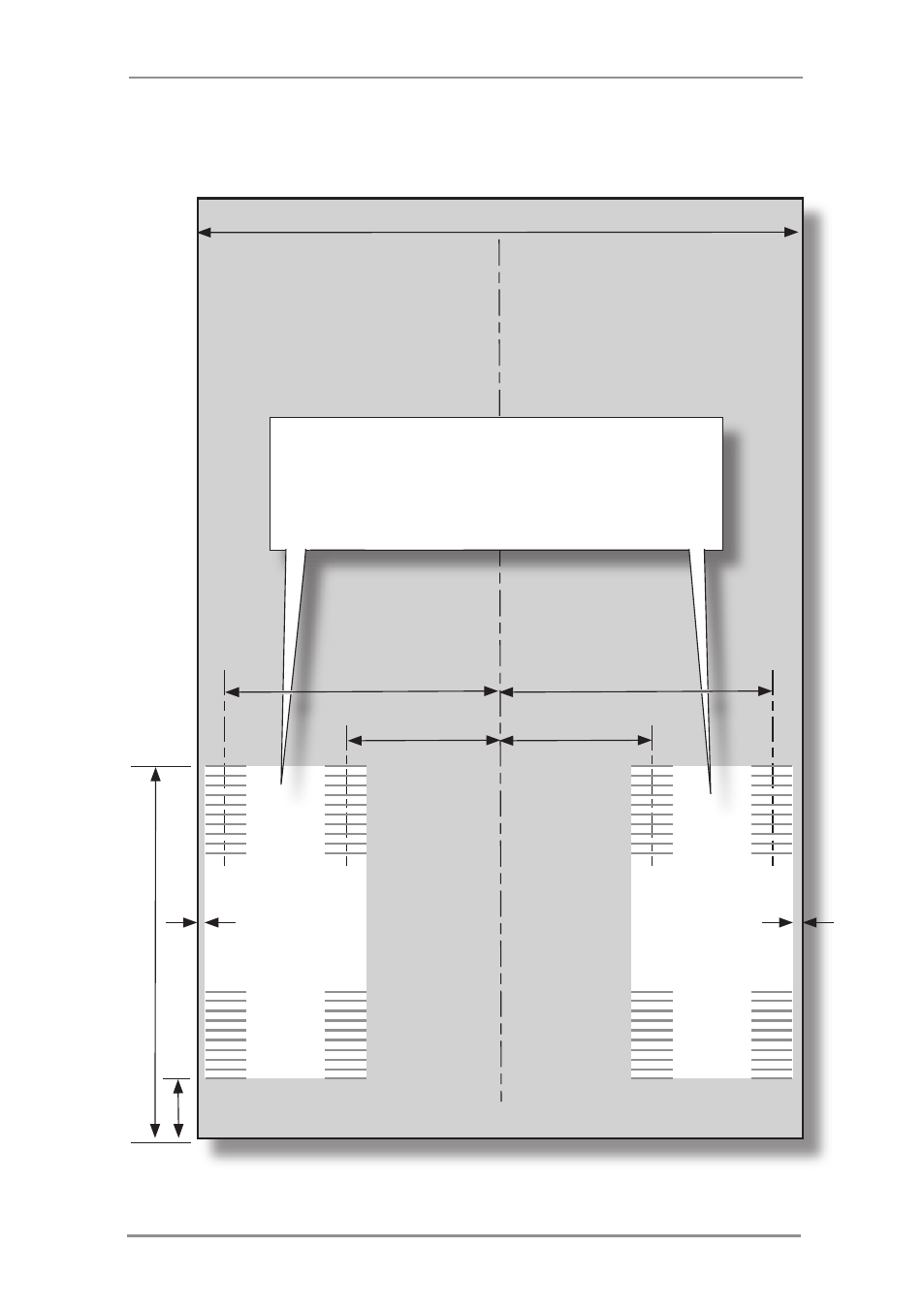
7” (176mm) min to 9” (229mm) max
Prime Sheet/Set OMR Code positions when using Single
or Z Fold with Selective Feed Only
LEADING EDGE
The white areas indicate possible locations
where OMR marks can be printed. This depends
on the physical positions of the scanners fitted to
the machine and the face of the sheet on which
the OMR marks are printed.
NOTE: A Clear Zone as specified on page 5-9 must
be allowed around the OMR marks.
3-1/8”
(80mm) min
4-3/16”
(107mm) max
This manual is related to the following products: