Explanation of symbols, Safety information, Intended usage – Parr Instrument 6200 User Manual
Page 7: General specifications, Preface
Preface
6200
w w w . p a r r i n s t . c o m
5
Safety Information
To avoid electrical shock, always:
1. Use a properly grounded electrical outlet of
correct voltage and current handling capability.
2. Ensure that the equipment is connected to
electrical service according to local national
electrical codes. Failure to properly connect may
create a fire or shock hazard.
3. For continued protection against possible
hazard, replace fuses with same type and rating
of fuse.
4. Disconnect from the power supply before
maintenance or servicing.
To avoid personal injury:
1. Do not use in the presence of flammable or
combustible materials; fire or explosion may
result. This device contains components which
may ignite such material.
2. Refer servicing to qualified personnel.
Intended Usage
If the instrument is used in a manner not specified
by Parr Instrument Company, the protection pro-
vided by the equipment may be impaired.
General Specifications
Electrical Ratings
120VAC, 6.0 Amps. 50/60 Hz
240VAC, 3.0 Amps. 50/60 Hz
Before connecting the calorimeter to an electrical
outlet the user must be certain that the electrical
outlet has an earth ground connection and that the
line, load and other characteristics of the installation
do not exceed the following limits:
Voltage: Fluctuations in the line voltage should not
exceed 10% of the rated nominal voltage shown on
the data plate.
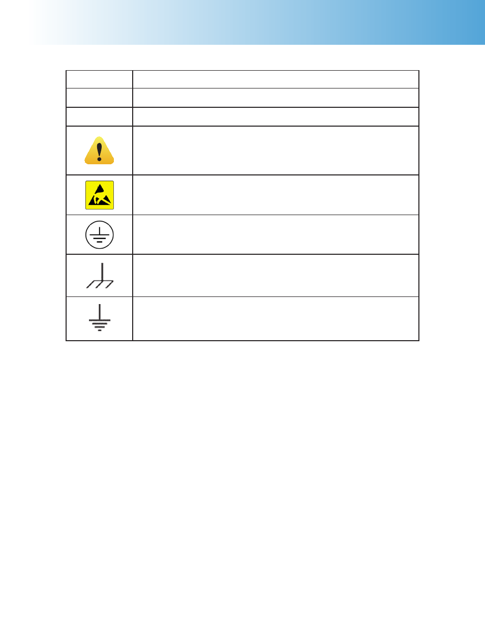
Explanation of Symbols
I
On Position
O
Off Position
~
Alternating Current
This CAUTION symbol may be present on the Product Instrumenta-
tion and literature. If present on the product, the user must consult
the appropriate part of the accompanying product literature for more
information.
ATTENTION, Electrostatic Discharge (ESD) hazards. Observe precau-
tions for handling electrostatic sensitive devices.
Protective Earth (PE) terminal. Provided for connection of the protec-
tive earth (green or green/yellow) supply system conductor.
Chassis Ground. Identifies a connection to the chassis or frame of the
equipment shall be bonded to Protective Earth at the source of supply
in accordance with national and local electrical code requirements.
Earth Ground. Functional earth connection. This connection shall be
bonded to Protective earth at the source of supply in accordance with
national and local electrical code requirements.