Figure 5 rj-45 pins definition for vfd*e*c models – Delta Electronics AC Motor Drives VFD-XXXE User Manual
Page 6
English- 6
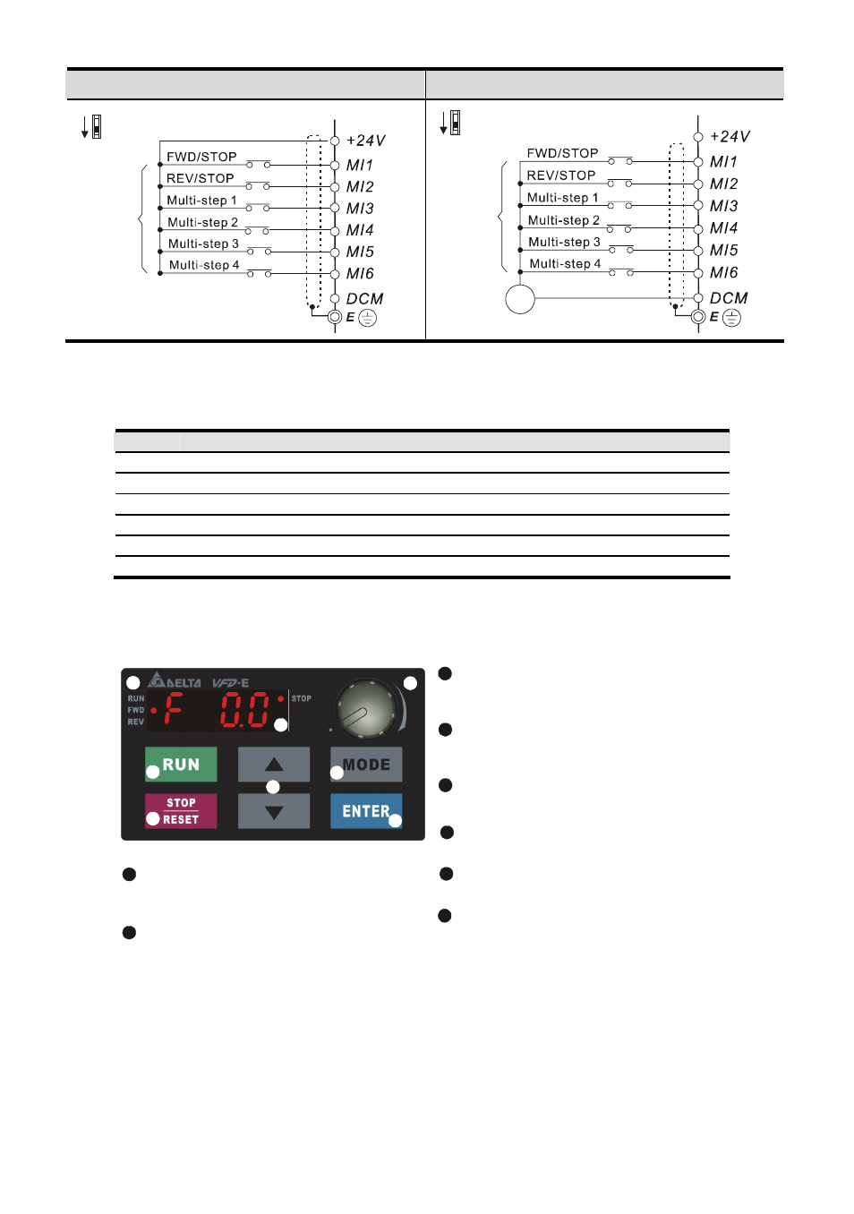
C. PNP mode without external power
D. PNP mode with external power
Sw1
Factory
setting
NPN
PNP
Sw1
Factory
setting
NPN
PNP
24
Vdc
-
+
Figure 5 RJ-45 Pins Definition for VFD*E*C Models
PIN
Signal
Description
1 CAN_H
CAN_H bus line (dominant high)
2
CAN_L
CAN_L bus line (dominant low)
3
CAN_GND
Ground / 0V /V-
4 SG+ 485
communication
5 SG- 485
communication
7
CAN_GND
Ground / 0V /V-
Description of the Digital Keypad KPE-LE02 (Optional)
LED Display
Indicates frequency, voltage, current, user
defined units and etc.
Status Display
Display the driver's current status.
STOP/RESET
Stops AC drive operation and reset the drive
after fault occurred.
RUN Key
Start AC drive operation.
MODE
Change between different display mode.
UP and DOWN Key
Set the parameter number and changes the
numerical data, such as Master Frequency.
Potentiometer
For master Frequency setting.
1
2
3
4
5
6
7
2
3
4
5
6
7
8
8
ENTER
Used to enter/modify programming
parameters
1
- 1x9 Bi-Directional Transceiver Module OPBD-155F2J1R (7 pages)
- Single Mode SFP Transceiver LCP-1250B4MDRx (14 pages)
- LC-1250xxxx Series (10 pages)
- Human Machine Interface DOP-AS Series (329 pages)
- Analog Output Module DVP04DA-S (2 pages)
- DeviceNet Slave Communication Module IFD9502 (2 pages)
- LCP-155B4MSRx (12 pages)
- High-Speed PCI 12-Axis Motion Control Card PCI-DMC-B01 (528 pages)
- Network Device DVP01PU-S (2 pages)
- GBIC-1250D5MR (12 pages)
- SPBD-1250A4Q1RT (10 pages)
- SILM4015 (1 page)
- LCP-8500A4EDR (14 pages)
- 10GBASE-SR SFP+ Optical Transceiver LCP-10G3A4EDR (16 pages)
- LCP-155A4HSRx (11 pages)
- LCP-1250RJ3SR-L (9 pages)
- SILM320L (1 page)
- LCP-1250RJ3SR-S (9 pages)
- SIL530 (1 page)
- Extension Digital I/O Module DOP-EXIO28RAE (1 page)
- DVP Series PLC DVP04TC-H2 (2 pages)
- 1x9 Bi-Directional Transceiver Module OPBD-155F1J1R (7 pages)
- Distribution Box TAP-CN01/02/03 (2 pages)
- LCP-200A4HSR (9 pages)
- Pulse Generation Unit DVP01PU-H2 (2 pages)
- Power Connection Interface VFD-PSD01 (1 page)
- Programmable Logic Controller DVP04DA-H2 (2 pages)
- Single Mode SFP Transceiver LCP-1250B4QDRx (13 pages)
- LCP-155B4JSRx Series (12 pages)
- Series Temperature Controller DTD Series (2 pages)
- Brake Modules BUE Series (2 pages)
- PLC DVP Series DVP-SX (2 pages)
- Digital Keypad / Display ASD-PU-01A (1 page)
- Multimode SFP Transceiver LCP-1250A4FDRx (14 pages)
- HMU1362M (1 page)
- RPA-01 (1 page)
- THMR1395 (1 page)
- SFBD-155F2J1RM (7 pages)
- Program Transfer Module DVP-PCC01 (1 page)
- RTU-DNET (41 pages)
- AC Servo Drive ASDA-AB (37 pages)
- Digital Keypad / Display ASD-PU-01B (1 page)
- HMR1045 (1 page)
- CANopen Communication Module DVPCOPM-SL (2 pages)
- SPBD-1250B4Q1R (10 pages)