Im 3, Basic wiring diagram – Delta Electronics AC Motor Drives VFD-XXXE User Manual
Page 4
English- 4
Storage/ Transportation
Temperature
-20
o
C to 60
o
C
Ambient Humidity
Below 90% RH (non-condensing)
Vibration 9.80665m/s
2
(1G) less than 20Hz, 5.88m/s2 (0.6G) at 20 to 50Hz
Approvals
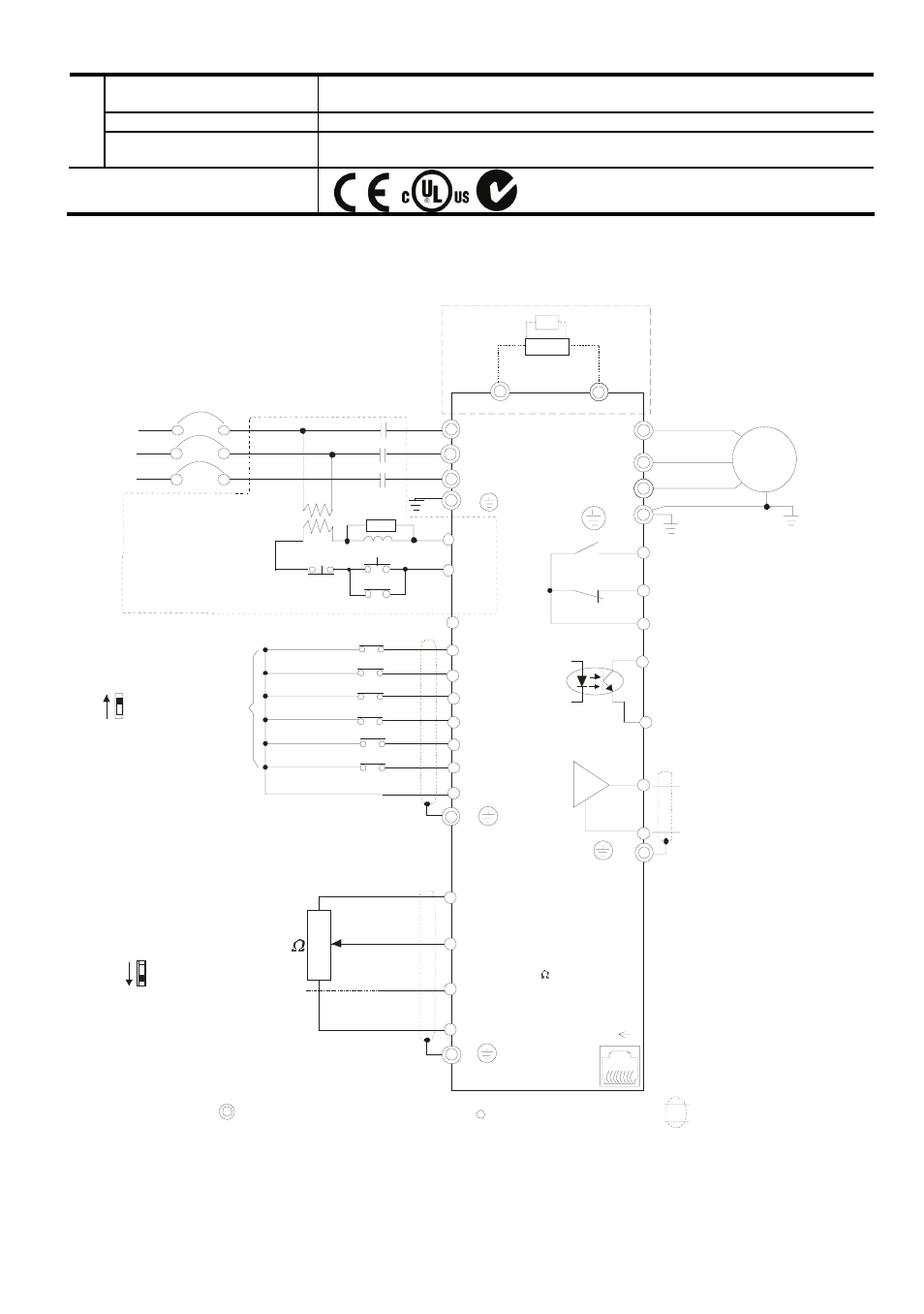
Basic Wiring Diagram
Users must connect wiring according to the following circuit diagram shown below.
AVI
ACI
ACM
+
4~20mA
+10V
5K
3
2
1
Power supply
+10V 3mA
Master Fr equency
0 to 10V 47K
Analog S ignal Common
E
Main c irc ui t (power) terminals
Contr ol c ircuit ter minals
Shielded l eads & Cable
* Don't apply the mains voltage direc tly
to abov e terminals.
E
R(L1)
S(L2)
T(L3)
F us e/NF B(None F use Br eaker)
SA
OF F
ON
MC
MC
RB
RC
Recommended Circ ui t
when power supply
is turned O FF by a
fault output
If the fault occ ur s, the
contact will be O N to
turn off the power and
protect the power sys tem.
R(L1)
S(L2)
T(L3)
E
Analog Multi- func ti on Output
Ter minal
factory setti ng: Analog fr eq.
/ c ur rent meter
0~ 10VDC/2 mA
U(T1)
V(T2)
W(T3)
IM
3~
AFM
ACM
RA
RB
RC
Motor
F ac tor y setting:
Driv e is in oper ation
48V50mA
Multi-function
Photocoulper Output
Analog S ignal common
E
E
Refer to Control
Ter minal Ex planation
MO1
MCM
MI1
MI2
MI3
MI4
MI6
MI5
DCM
+24V
F WD/Stop
REV/Stop
Multi-s tep 1
Multi-s tep 2
Multi-s tep 3
Multi-s tep 4
Digital Si gnal Common
F ac tor y
setting
Sw2
AVI
ACI
F act ory set tin g:
ACI Mod e
ACI/AVI sw itch
Wh en switch in g to AVI,
it in dicates AVI2
-
8 1
Sw1
NPN
PNP
F act ory set tin g:
NPN Mo de
Please refer to f ollow in g
fig ure fo r wirin g of NPN
m od e an d PNP mo de.
Br ak e r es istor/unit ( optional)
Refer to us er manual for the us e
of spec ial brak e res istor/unit.
T he wiring for the models
may be differ ent. Refer to
following figures for detail.
* Single-phase models can only use R(L1), S(L2) to be the power terminals.
* Single-phase power cannot be used for 3-phase models.
BUE
Br ak e unit
( optional)
BR
brake re sistor
(opt ional)
RS-485 serial inter face
(NO T for VF D*E*C models)
1: Reserv ed
2: EV
5: SG +
6: Reserv ed
7: Reserv ed
8: Reserv ed
3: G ND
4: SG -
F or VFD*E*C mo dels,
p lease ref er t o figu re 5.