Lingenfelter L460240000 Lingenfelter NCC-002 Nitrous Control Center v1.5 User Manual
Page 28
Lingenfelter NCC-002 Nitrous Control Center Installation and Operating Instructions
27
3.1.7
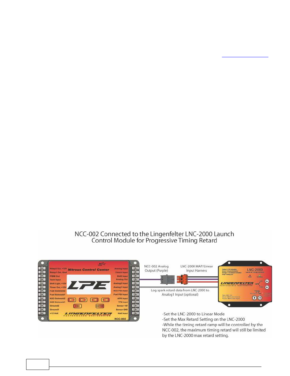
NCC-002 Connected to the LPE LNC-2000 Launch Controller
Use this wiring configuration to allow the NCC-002 to output a progressive signal to the LPE LNC-2000 Launch
Control Module. This collaboration between the controllers creates progressive spark retard. The optional LNC-
2000 then can send spark data back to the NCC-002 where the data is logged. See the
LNC-2000 instructions
for more information regarding the wiring and settings of the LNC-2000.
NOTE: The female connector that is used to connect the NCC-002 to the LNC-2000, as shown in the
wiring diagram below, is not necessary in order to connect the NCC-002 to the LNC-2000. LPE is
currently developing an adapter harness that will allow the analog out signal from the NCC-002 to reach
the analog input on the LNC-2000 without the need to modify the wiring. Until that adapter harness is
released, the LNC-2000 Analog Out wire (purple) should be taken out of the male harness connector and
connected to the NCC-002 as described in the instructions below.
NOTE: Each terminal on the NCC-002 controller is capable of connecting to 2 separate wires at a time.
If there are more than two wires going to a single terminal (as may be the case with the sensor ground
terminal), splice the incoming wires together. Another option is to purchase a barrier strip adapter that
allows the single terminal to connected to another barrier strip for increased capacity.
1) If connecting the LNC-2000 to the NCC-002 without an adapter:
•
Extract the purple wire from the LNC-2000 male harness connector.
•
Splice the solid purple wire (LNC-2000 Analog input) from the LNC-2000 with the solid purple wire labeled
"ANALOG OUT" supplied in the NCC-002 wiring harness. Connect the spliced purple wire to the "Analog Out"
terminal on the NCC-002 controller
•
Optional: To log timing retard, connect the solid gray wire (Analog Out) from the LNC-2000 to the "Analog1
Input" terminal on the NCC-002
2) If installing the LPE female harness connector:
•
Connect the solid purple wire (Analog Out) from the NCC-002 harness to the B (middle) terminal on the
female harness connector.
•
Connect the female harness connector to the orange LNC-2000 MAP sensor male connector.
•
Optional: To log timing retard, connect the solid gray wire (Analog Out) from the LNC-2000 to the "Analog1
Input" terminal on the NCC-002