Fig. 4.3 – EZ-ACCESS PASSPOR User Manual
Page 9
Page | 9
3. The guard ramp activating bar is shipped with the platform. Locate the guard ramp activating bar splice
connector and
the 5/16”-18 x 1” long assembly bolts in the hardware bag then assemble the guard
ramp activating bar as shown in FIG. 4.2. Do not tighten the assembly bolts fully until after the
activating bar is attached to the tower.
4. Determine which side of the platform will have the guard ramp and attach the guard ramp activating bar
in the two open holes on the corresponding side of the tower
using two 5/16”-18 x 1” long attachment
bolts. The guard ramp activating bar must always be installed on the same side as the guard ramp
(FIG. 4.1). Tighten all fasteners, including the splice connector bolts, securely.
The 90° Turn Platform guard ramp activating bar extends further from the tower than the Straight
Platform guard ramp activating bar. The extension for the Straight Platform is approximately 7-
7/8”
and approximately 12-
3/8” for the 90° Turn Platform. The correct guard ramp activating bar must be
used with its intended platform for the guard ramp to operate correctly.
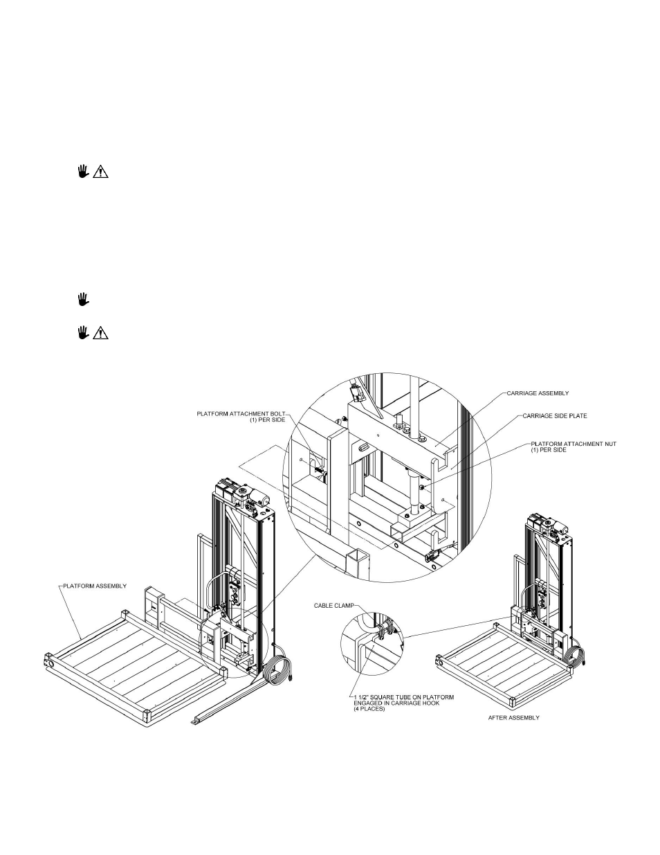
5. L
ift the platform assembly onto carriage engaging both 1½” square tubes on the platform to the
corresponding hooks in the carriage. Locate the two
5/16”-18 x 1-1/2” attachment bolts and locknuts in
the hardware bag and install through the mating holes in the platform assembly and the carriage side
plate then tighten securely (FIG. 4.3).
The outer cable clamp holding the control box wire bundle may need to be removed from the
carriage to fully engage the platform tubes.
Never lift or carry the platform using the safety pan. Damage to the safety pan sensors can occur
rendering the lift unsafe or inoperable.
FIG. 4.3