Fig. 4.15, Fig. 4.15a – EZ-ACCESS PASSPOR User Manual
Page 17
Page | 17
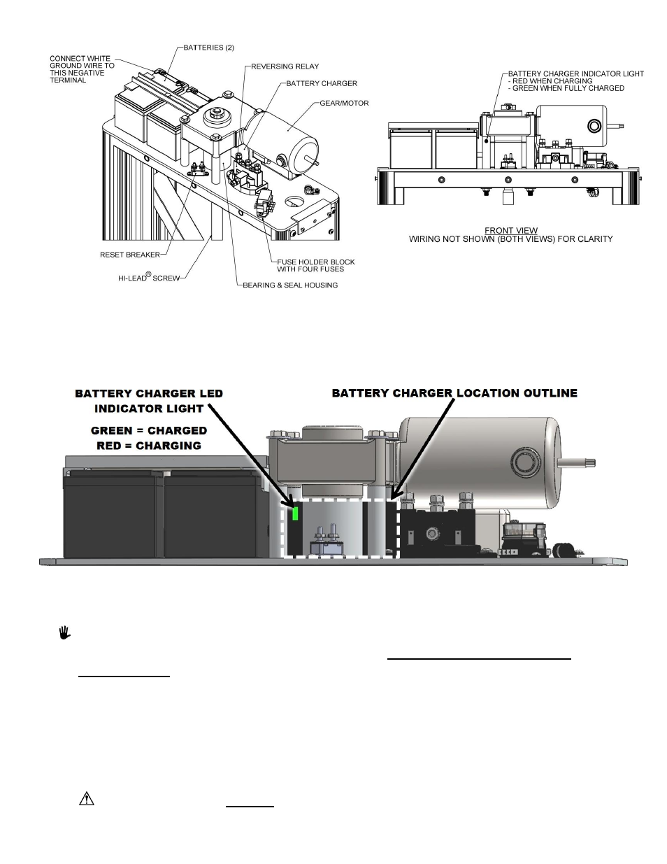
FIG. 4.14
FIG. 4.15
32. Turn the keyed master switch to the Power
“OFF” position, remove key and disconnect VPL from AC
power.
33. Reinstall the back cover panel at this time.
FIG. 4.15A
THE VPL IS NOW READY TO SET IN PLACE - VPL PLACEMENT AND INSTALLATION:
IF USING THE VPL WITH A TOP LANDING GATE, PROCEED TO THE TOP
LANDING GATE INSTALLATION SECTION PRIOR TO PLACING AND
INSTALLING THE VPL.
34. Position the VPL in its approximate final position. The gap between the fascia and the edge of the
VPL
platform is required by code to be between 3/8” and 3/4”.
35. Plug VPL into AC power, reinsert key into the keyed power switch and turn to the Power
“ON”
position.
36. Run the VPL Platform up to the upper landing height. If supplied the optional Call/Send Control, use
the Call/Send Control to operate the VPL. If a Call/Send Control is not included, use a ladder or other
means to operate the control.
Do not operate the VPL occupied until it is anchored in place. Anchoring the VPL must be
completed before running occupied.