Fig. 11.3, Fig. 11.4, Fig. 11.5 – EZ-ACCESS PASSPOR User Manual
Page 39: Fig. 11.6
Page | 39
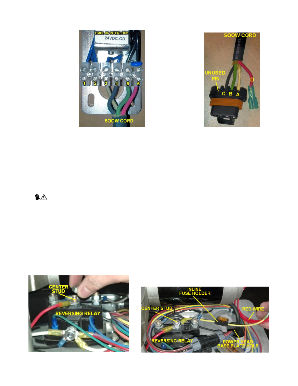
INTERLOCK ELECTRICAL CONNECTIONS:
Terminal
Terminal
Terminal
Terminal
Terminal
Terminal
1
2
3
4
5
6
Unused
Unused
White
Black
Green
Red
A = White
B = Green
C = Black
D = Red
FIG. 11.3
FIG. 11.4
INSTALLATION PREPARATION:
Strip the 18/4 SOOW
cord to expose ½” of copper conductor (see FIG. 11.2 and 11.5). Remove the cover from
the Porta Electric EMDL 06 door interlock and connect the wires from the SOOW cord as shown in FIG. 11.3.
INSTALLATION:
1. Turn VPL Keyed P
ower Switch to the “OFF” position, remove key, and unplug VPL from AC power.
Failure to turn the VPL Keyed Power Switch to the
“OFF” position and remove key and unplug AC
power cord could create a dangerous situation and result in equipment damage or failure, injury
to property, risk of electrical shock, risk of fire, risk of crushing injuries, risk of serious personal
injury, or death.
2. Remove the power head plastic cover. (FIG. 4.1).
3. Disconnect white 10 gauge ground wire from negative battery terminal (FIG. 4.9).
4. Leaving control box connected, remove rear platform guard wall and set it on surface that will not
scratch the guard wall (FIG. 4.6).
5. Remove front and rear cover panels from lift tower. (FIG. 4.1).
6.
Remove ½” nut from center stud on reversing relay. (FIG. 11.5).
7.
Install 5/16” ring terminal on yellow wire with inline fuse holder over center stud. Replace nut, tighten
securely. (FIG. 11.6).
FIG. 11.5
FIG. 11.6