Fig. 6.2 – EZ-ACCESS PASSPOR User Manual
Page 25
Page | 25
3. The area between the ground and the porch or deck where the VPL Platform will travel must be closed.
Consult local building codes and close this area as required.
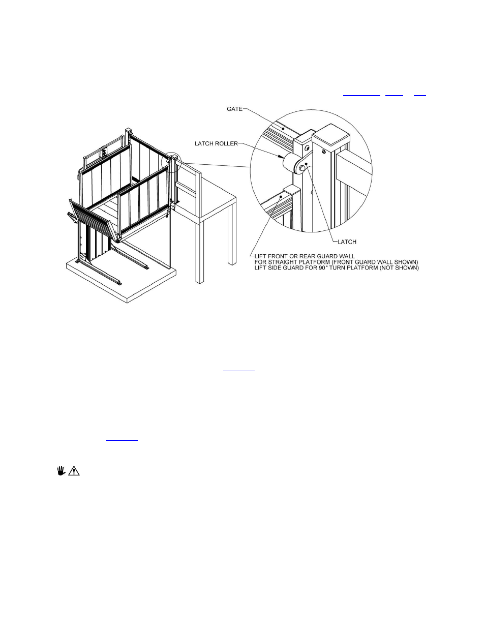
4. Install the VPL as described elsewhere in the manual. The side of the VPL platform adjacent to the
fascia
must be between 3/8” and 3/4” of the porch or deck and the front or rear guard wall of the
straight platform or the side guard wall of the 90° Turn Platform must align with the latch roller on the
Top Landing Gate depending on which way the Top Landing Gate opens (
FIG. 6.2
5. Complete the remaining steps in Section 4, Assembling the VPL, Steps 33 through 51.
6. After completing the VPL installation, place the Top Landing Gate on the porch or deck and adjust its
position side to side until the front or rear guard wall of the platform aligns with the latch roller on the
Top Landing Gate without hitting the latch (
). It is recommended that this be done with weight
on the VPL Platform approximately equal to the VPL user’s weight since the platform has a built in 1°
angle which may affect the alignment.
7. Once the Top Landing Gate is positioned correctly it can be attached to the porch or deck. The Top
Landing Gate will come with four 1/4” self-drilling screws for attaching the Top Landing Gate sill to the
deck surface and two 5/16”-18 x 4-1/2” long hex bolts for attaching the Top Landing Gate sill to the
deck fascia (
). If the Top Landing Gate is being attached to a concrete porch or deck these
screws and bolts will need to be replaced with concrete anchors and alternate fasteners of the same
size (not included).
Follow the concrete anchor
manufactures’ installation instructions when using concrete anchors.