Getting started, Stp-10 hardware manual, Stepper software application. bimba iq – Bimba STP-10 User Manual
Page 5: Stepper contains a link to the iq
STP-10 Hardware Manual
5
Getting Started
This manual describes the use of six different drive models. What you need to know and what you must have depends on the
drive model. For all models, you’ll need the following:
• A 24-48 volt DC power supply. Please read the section entitled Choosing a Power Supply for help in choosing the right power
supply.
• A compatible Bimba stepper motor. See section on Recommended Motors.
• A small flat blade screwdriver for tightening the connectors (included).
• A personal computer running Microsoft Windows 98, 2000, NT, Me, XP, Vista or 7.
• A Bimba programming cable (included with non-Ethernet drives).
• For Ethernet drives, you will need a CAT5 cable (not included).
• Relevant software applications, as outlined below. All software is available as a free download from .
If you’ve never used a STP drive before, you’ll need to get familiar with the drive and the set up software before you try to deploy
the system in your application. We strongly recommend the following:
1. For -S drives, -Q drives, and -EIP drives, install the IQ
®
Stepper software application. Bimba IQ
®
stepper contains a link to the
IQ
®
Programmer software applications.
2. Launch the software by clicking Start...Programs...Bimba...
3. Connect the drive to your PC using the programming cable. For RS-232 drives, select the correct COM port. For Ethernet
drives, ensure that the IP address is correct. See page 7 of this manual for more information on “Connecting the Drive to Your
PC using Ethernet.”
4. Connect the drive to the power supply.
5. Connect the drive to the motor.
6. Apply power to the drive.
7. The software will recognize your drive, display the model and firmware version and be ready for action.
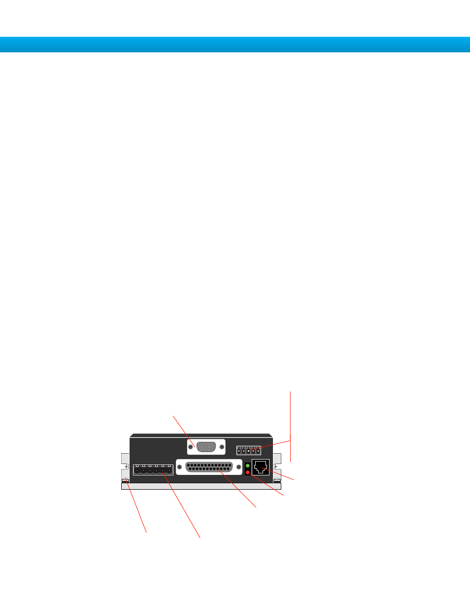
The connectors and other points of interest are illustrated below. Depending on your drive model and application, you’ll need to
make connections to various parts of the drive. These are detailed later in the manual.
screw terminal
connector
•
motor
•
power supply
DB-25 connector
•
digital inputs
•
digital outputs
•
analog input
screw terminal
connector
•
optional RS-485 port
HD-15 connector
•
optional encoder feedback
RJ11 connector
•
RS-232 port
LEDs
•
status & error codes
grounding
screw
spring terminal
connector
and rotary switches
RJ45 connector and
rotary address switch
•
optional Ethernet interface