Stp-10 hardware manual, Pin assignments (facing drive), Internal circuit – Bimba STP-10 User Manual
Page 17: Hd-15 connector
STP-10 Hardware Manual
17
Connecting an Encoder (Requires the Optional Encoder Feedback Card)
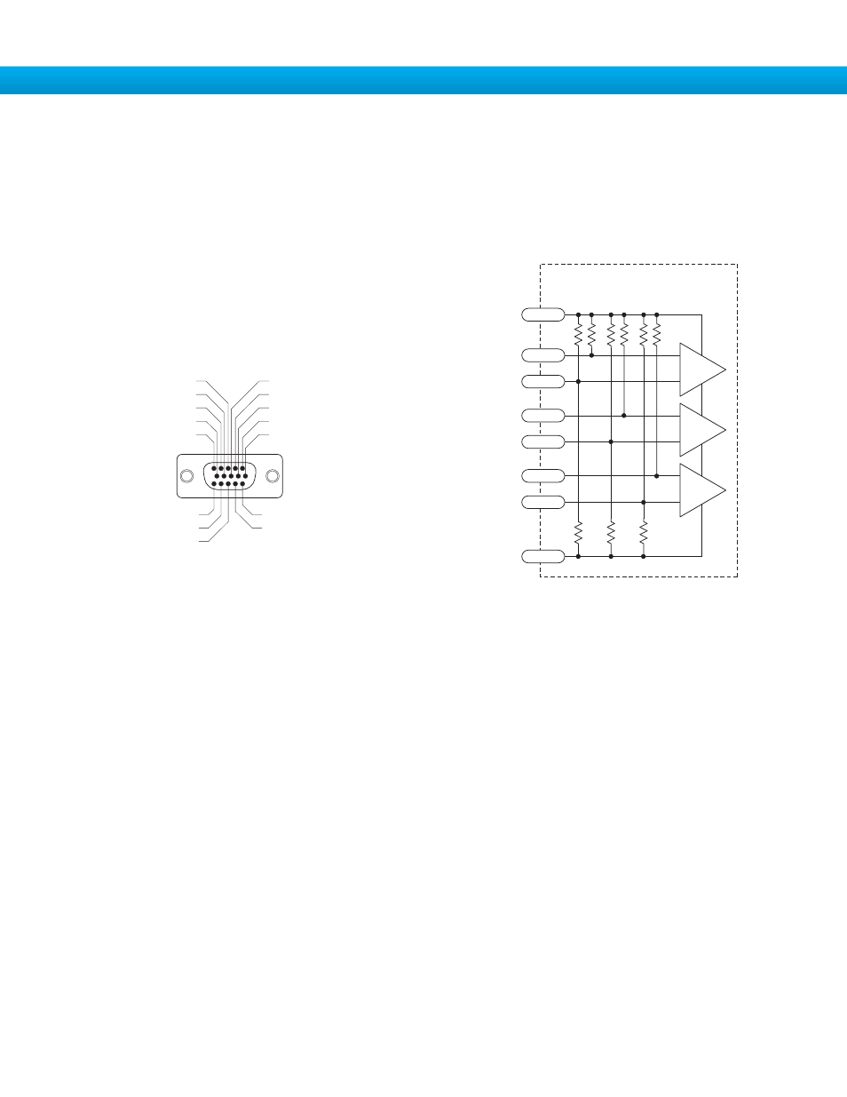
The encoder connections use a HD-15 connector, which you must connect to your encoder as shown below. See back page for
mating connector information.
If your encoder is single ended, connect the encoder outputs to the A+, B+ and Z+ inputs. Leave A-, B- and Z- unconnected. (Z
is the encoder index signal and is optional.)
Pin Assignments (facing drive)
encoder Z+ (5)
do not connect (10)
encoder B- (4)
do not connect (9)
encoder B+ (3)
do not connect (13)
do not connect (14)
shield (15)
(12) do not connect
(11) do not connect
(6) encoder Z-
(1) encoder A+
(7) +5VDC 200mA
(2) encoder A-
(8) GND
Front View
Internal Circuit
inside drive
A-
A+
2
GND
8
1
+5V
7
HD-15 Connector
B-
B+
4
3
Z-
Z+
6
5
5K
12.5K
8.3K
5K
12.5K
8.3K
5K
12.5K
8.3K