Connecting limit switches, Wiring a mechanical limit switch, Wiring a limit sensor – Bimba STP-10 User Manual
Page 23: Stp-10 hardware manual
STP-10 Hardware Manual
23
Connecting Limit Switches
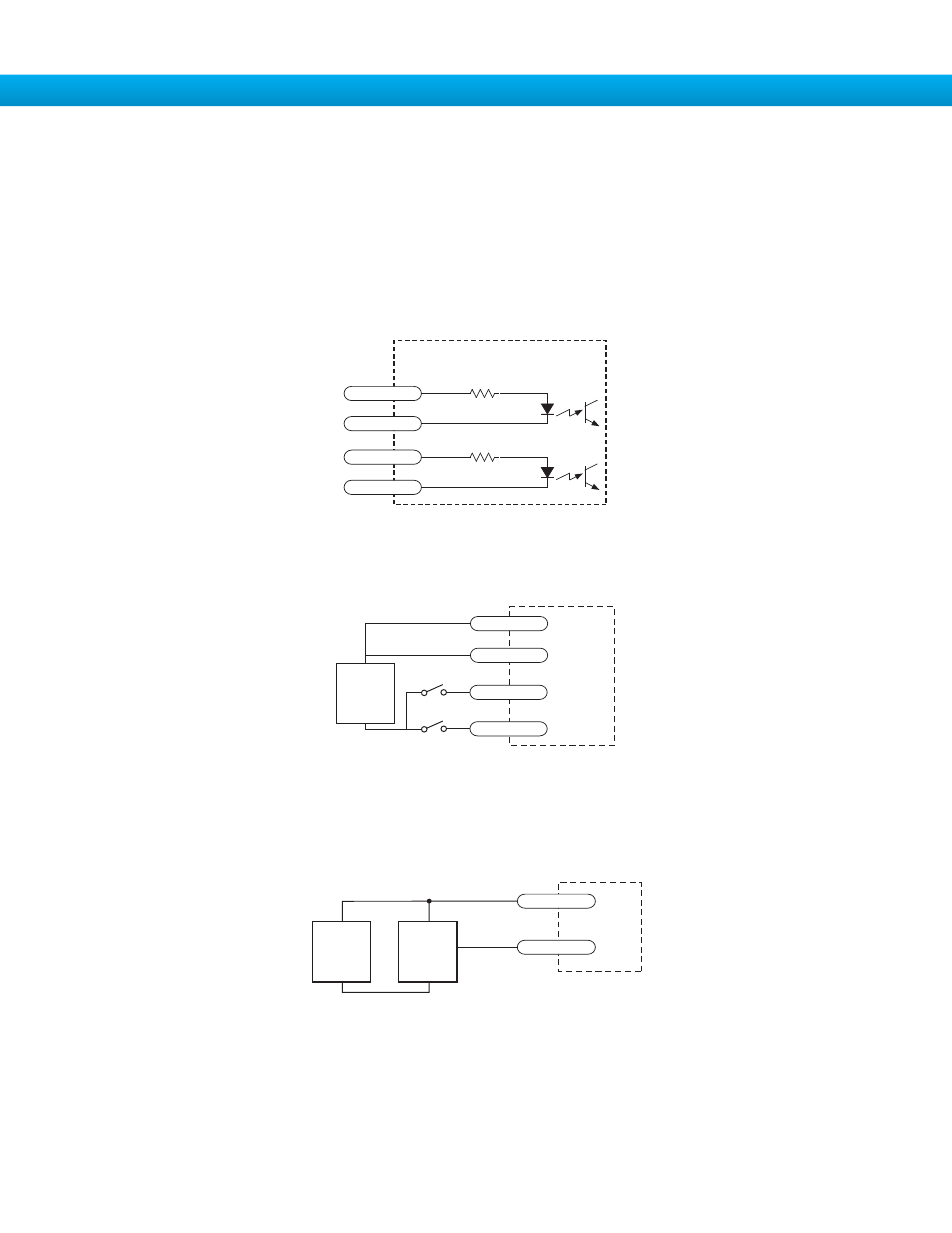
The CWLIMIT and CCWLIMIT inputs are used for connecting end of travel sensors. These inputs are differential, which allows
you to use signals that are sinking (NPN), sourcing (PNP) or differential (line driver). By connecting switches or sensors that are
triggered by the motion of the motor or load, you can force the motor to operate within certain limits. This is useful if a program or
operator error could cause damage to your system by traveling too far.
The limit inputs are optically isolated. This allows you to choose a voltage for your limit circuits of 12 to 24 volts DC. This also al-
lows you to have long wires on limit sensors that may be far from the drive with less risk of introducing noise to the drive electron-
ics. The schematic diagram of the limit switch input circuit is shown below.
Wiring a Mechanical Limit Switch
You can use normally open or normally closed limit switches. Either way, wire them as shown here. Be sure to set the polarity us-
ing the IQ
®
Stepper software for the STP-10-Q.
Wiring a Limit Sensor
Some systems use active limit sensors that produce a voltage output rather than a switch or relay closure. These devices must be
wired differently than switches.
If your sensor has an open collector output or a sinking output, wire it like this:
DRIVE
+
DC
Power
Supply
–
Limit
Sensor
output
+
–
CW LIMIT+
CW LIMIT-
DRIVE
+
12-24
VDC
SUPPLY
-
CW LIMIT+
CW LIMIT-
CCW LIMIT+
CCW LIMIT-
inside drive
2200
X8/CCWLIM-
25
X8/CCWLIM+
24
2200
X7/CWLIM-
23
X7/CWLIM+
22