Analog inputs, Stp-10 hardware manual, Drive – Bimba STP-10 User Manual
Page 24: Gnd ain +5v out, Ain2, Connecting a potentiometer to analog input 1, Db-25 connector
STP-10 Hardware Manual
24
DRIVE
+
DC
Power
Supply
–
Proximity
Sensor
output
+
–
CW LIMIT+
CW LIMIT-
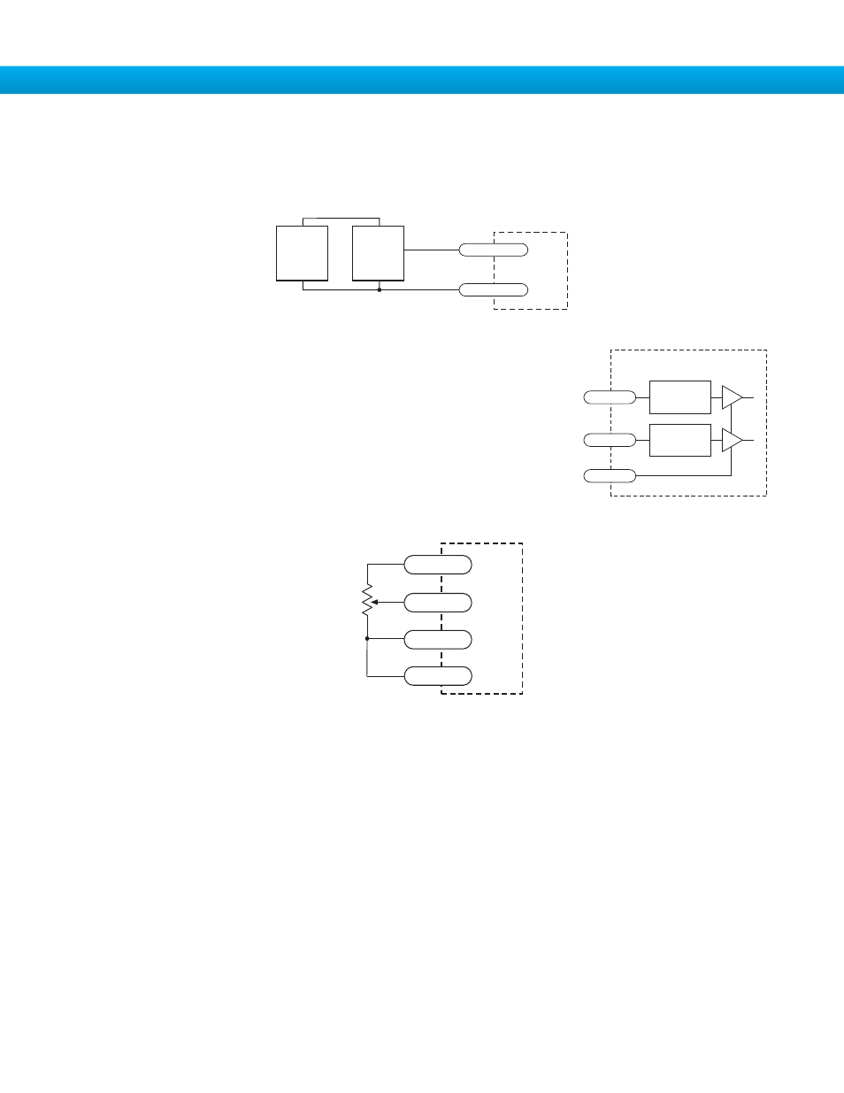
Connecting a Potentiometer to Analog Input 1
Analog Inputs
The STP drives feature two analog inputs. Each input can accept a signal range of 0
to 5 VDC, ±5 VDC, 0 to 10 VDC or ±10 VDC. The drive can be configured to operate
at a speed or position that is proportional to the analog signal.
A shielded cable is recommended for electrically noisy environments.
Use the IQ
®
Stepper software to set the signal range, offset, deadband and filter fre-
quency.
inside drive
AIN1
AIN2
GND
1
2
13
DB-25 Connector
Signal
Conditioning
Signal
Conditioning
1-10kW
pot
cw
ccw
DRIVE
GND
AIN
+5V OUT
18
1
13
AIN2
2
If the sensor output goes low at the limit, select the option “closed” (in the software). If the output is open, or high voltage, choose
“open”.
Other sensors have sourcing outputs. That means that current can flow out of the sensor output, but not into it. In that case, wire
the sensor this way: