After do data are ready, do-req signal is asserted, 50 function block and operation theory, Pcie-7350 card – ADLINK PCIe-7350 User Manual
Page 60
50
Function Block and Operation Theory
Step2: Execute DO DMA Write Command (burst handshaking
mode)
The DO data saved in the system memory will be trans-
ferred to DO FIFO directly and automatically by bus master-
ing DMA.
After DO data are ready, DO-REQ signal is asserted.
PCIe-7350 start to send DO data and DO sampled clock to
external device after DO-ACK signal is asserted.
If input buffer of external device has no much space for new
DO data, DO-ACK signal will be inactive and PCIe-7350 will
be only allowed to send 4 more data to the receiver.
If DO data are not ready (DO FIFO is empty), DO-REQ sig-
nal will be inactive and PCIe-7350 stops to send DO data
and DO sample clock until DO data are ready again.
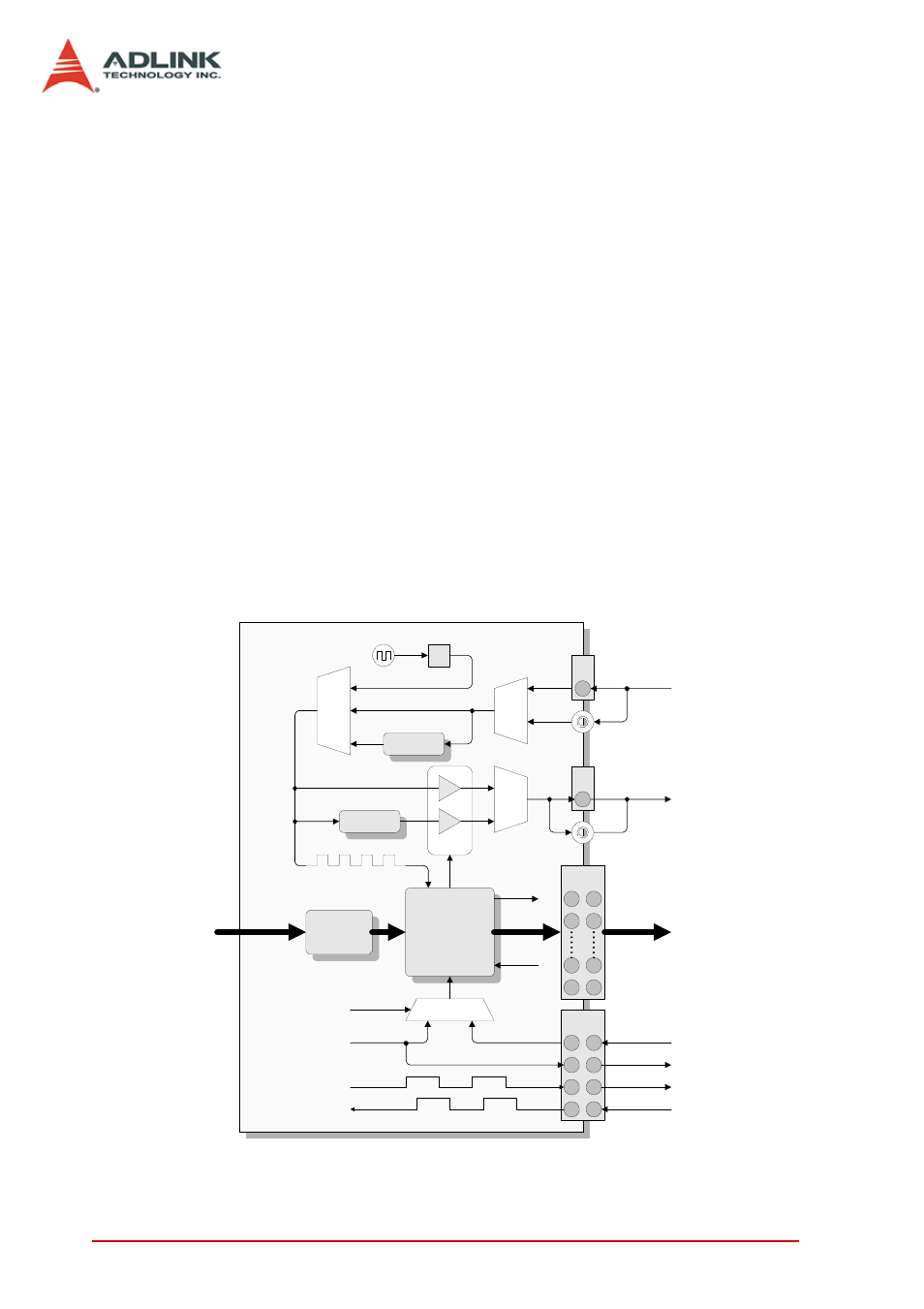
The operation architecture of DO DMA in burst handshaking mode
is shown as below:
Figure 3-20: DO Burst Handshaking Mode Architecture
1/N
DO CL
K
Mu
x
Int. DO sampled clk
16 steps
phase shift
Ext. DO sampled clk
E
xt.
DO
CLK
Mu
x
Bus Master DMA
100MHz
8K FIFO
Flip Flop
D[31:0]
I
AFI6
SMB CLK in
AFI[7:0]
DO sampled clk
Start Trigger
Mux
NoWait/
WaitTRIG
Software trigger
DO-Start or DO-TRIG
PCIe-7350 Card
DO Data
DO Data
External trigger in
External clock in
clk
enable
16 steps
phase shift
O
AFI6
Exp
o
rt.
D
O
C
L
K
Mu
x
SMB CLK out
Exported sampled
clock out
clk valid
Export
clk gate
Software trigger out
DO-REQ
DO-ACK
DO-REQ
DO-ACK
DO-REQ
DO-ACK