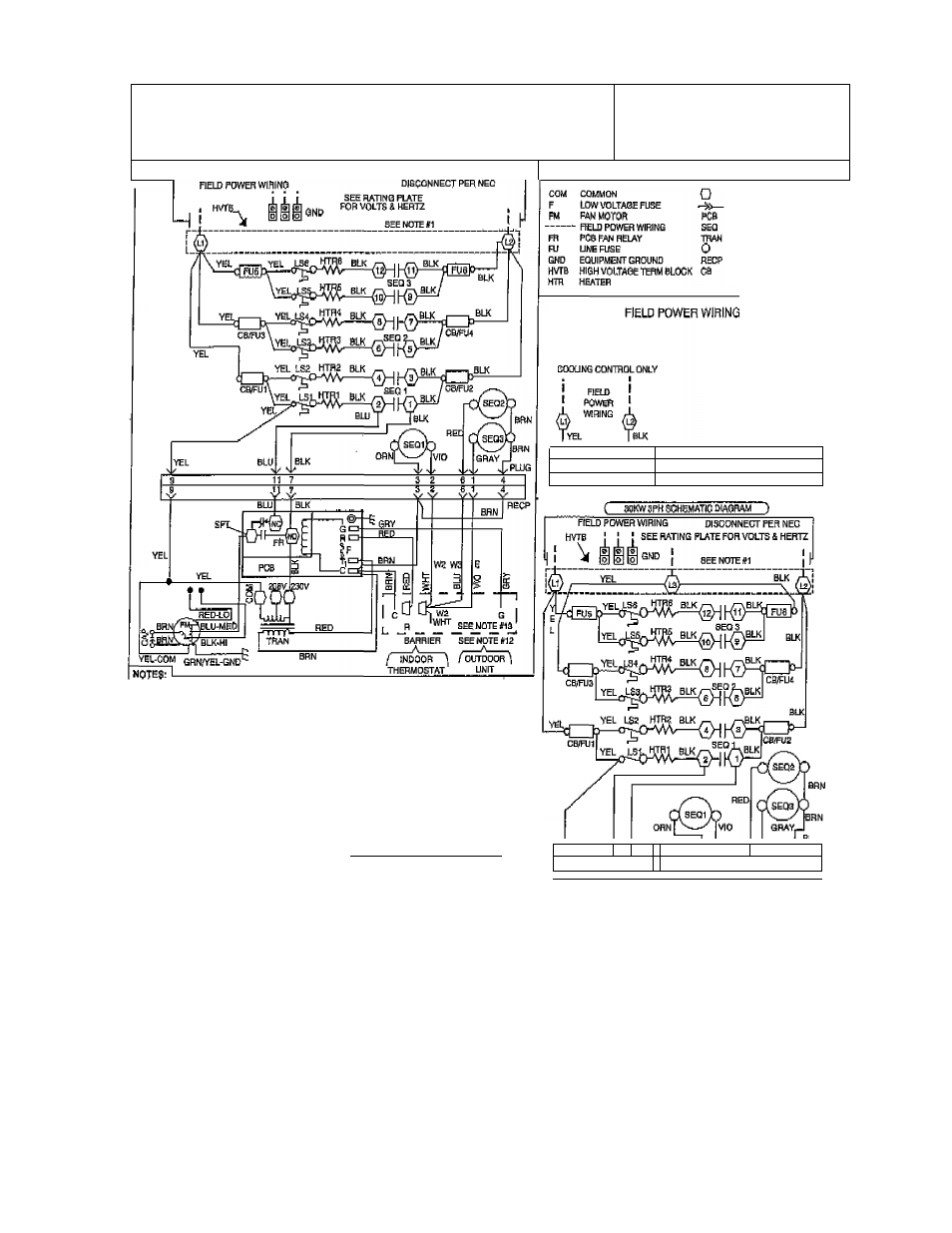
Pig. 4—^wiring diagram, Utc tech pub – Bryant FA4A User Manual
Page 5
Attention! The text in this document has been recognized automatically. To view the original document, you can use the "Original mode".
A П П G / 1 4 / 2 0 0 8 / T H U 0 3 : 4 6
UTC TECH PUB
) . 3 1 7 2 4 0 5 6 6 2
P ,
f
THIS COMPARTMENT MUST BE CLOSEP EXCEPT TOR SERVICING
1 BLOWER MOTOR |
.„.J
ROTATION
CAUTION: ^
NOT SUITABLE FOR Ь5Й ON SYSTElilS EXCEEOINS
leovTO GROUND
ATTENTION:
C
bo
KW 1PH SCHEMATIC DIAGRAM)
LEGEND
MARKED TERMINAL
PLUS AND RECEPTACLE
PflINTSD CIRCUIT BOARP
SEQUENCER
TRANSFORMER
UNMARKED TERMINAL
RECEPTACLE
CIRCUIT BREAKER
в 117
Я p e
1
i
£0B/240VAC
24VAC 24VAC
3 11 7 U
U 3 2 8 1 4
USE COPPER WIRE (/S'C MIN) ONLY BETWEEN D[SCCNNECT 3WIT01 AND UNFT,
TO BE WIRED IN ACCORDANCE WITH NEC AND UDCALOODES,
i, TRANSPORMER PRIMARY LEADS, BLUE 20aV, RED 230V.
A IF ANY OFTHE ORIGINAL WIRE, AS 5UPPUED. MUST BE REPLACED,
USE THE SAME OR RQUIVACPJTTYPE WIRE.
REPLACE LOW VOLTAGE FUSE WITH NO GREATER THAN 5 AMP FUSE.
20KW HEATER USES ONE DOUSLg POLE LS ON MIDDLE TOP ELEMENT.
10, Й4 AND 30KW HEATERS USE СЮиВ1^ POLE UHIT SWITCHES.
LARGEST HEATERS ARE SHOWN, SMALLER HEATSR5 Will HAVE FEWER ELEMENTS AND
COMPONENTS.
1 PHASE HEATERS ARE SHOWN WIRED FOR 8INSL£ SUPPLY CIRCUIT.
10. USE SO AMP CLA38 К FUSSS ONLY. FOR REPLACEMENT.
11, (3) SPEED MOTOR SHOWN. OPTIONAL (2) SPEED MOTOR иЗЕЗШ(ВЦ^ AND LOW
(BLU OR RED).
13, CONNECT fi TO R, S TO G, ETC.. SEE OLnDOQR INSTRUCTION FOR DETAILS,
la. IF WIRE CRIMP IS REMOVED AN EMEHOENCV HgATftgUY 16 REQUIRED.
(SEE OUTDOOR-THERMOSTAT (NSTRUCTIOMS)
32121A-101 REV. C
■ 9 ■■ '■■ ■ 1
1
3^ 6 1 4
2DB;S4aVAC
J 24VAC 24VAC
pig. 4—^Wiring Diagram
A9434G
3, Check low-voltage fuse shown in Fig. 3. Jf fuse is blown,
replace it. The transformer cannot supply power to board
with fuse bjowfl or loose. If fuse blows when unit has pow‘er
applied to it, the systejs most likely has 1 of the following
problems:
a. Check all 24-v wiring for an electrical short.
b. The maximum load on transfonner is 40 va. If load ott
transformer is excessive, the low-voltage 5-anjp fuse
will blow to protect transformer. If load exceeds va
rating of transformer, a larger va rated transformer needs
to be installed. Check sequencers for excessive current
draw.
C, Check wiring of heaters. If a heater is miswired, fuse
may blow. If a heater is miswired, correct miswiring by
comparing it to heater wiring label.
4. Check connections on primary side of transfonner. If they
arc not connected properly, the low-voltage terminal board
cannot supply the 24-v signal to energize fan
relay.
If
transfonner is receiving correct primary
voltage
hut is not
putting out correct secondary
voltage,
transformer needs to
be replaced.
-
5
-