320486-301 rev. c, О о о о, L i y – Bryant FA4A User Manual
Page 12: T вштоента, Я,о^ рсв, Legend
Attention! The text in this document has been recognized automatically. To view the original document, you can use the "Original mode".
AÏÏG/14/2008/THÏÏ 03:47 PM UTC TECH PUB
FAX No. 317 240 5662
P. 012
■mis COMPARTMENT
must
be
closed
except
for
servicing
CAUTION:
hfOT SUITABLE FOR USE OW SYSTEMS
exceeding
150V
to
ground
ATTENTION:
NE CONVIENT FAS AUX INSTALLATIONS
DE PLUS DE 150 V A LA TERRE
&DKW IPH SCHEMATIC PI AG RA^O
fjliHEMATia OlAflftAM
FIELi]
WIFtlrJÜ
DISCONNECT PER NEC
-H !
üSâ rtAïiNiï
plate
3
____ _____ _ j.
c
FIELD POWER WIRING
1
QlfiCONHECT PER NEC
|oND
I
SEE RATIHQ PLATE
pgn VÛLT3 t HERTZ
[5E5 NPT41)
?=
( cot^jjHceoNTBQL wifliHa 1
COQLINa CONTROL ONLY
PH ■
Л
__j_
L
am
PLUE 1 ПЁЬ
PLUlj Я
----------- VIÜ
/
BLU
/
ПА 1И
/
/
----------- QRY
-----------
red
AUX HEAT RANGE
4-0 о ,o О
ACЛ^P SIÎR
О О ofâ
туре
^
AJ HP-COMFORT HP-CFF g]—
RED
BLK
О о
... .
HCIHP
CFM TRIM
—О
©
© ©“
АС/HP DELAY OW/OFF
Oran ЗПРГ1г 30Î3D □/□
О О О О
о
йЁса^Х^ _______
О-
©-
(|Н - -
©т----------
—®
5ЯС1 *=* AUX1 HUM1
оо
оо
AUKÏ
ниш
ЯЭйгтТтГ
-BLU^ RECP1
.я,о^ РСВ
щ.
INDOOR THERMOBTAT
\
O
y
^L I Y". .
ЮфффффШф
blk
T вшТоенТа^
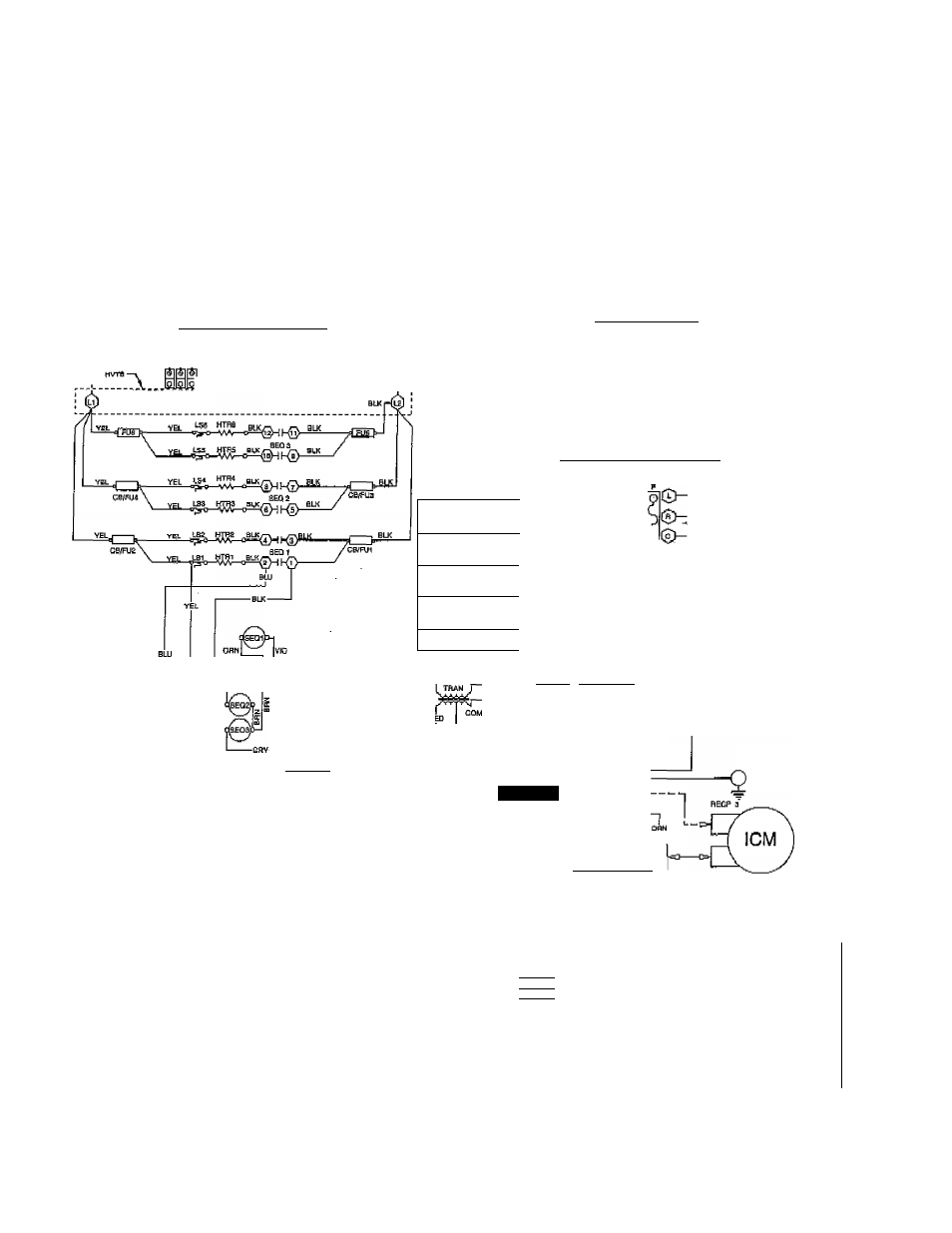
NOTEfi:
1
1
U80 copper Wire only between dleconnect ewHoh unit.
2. Connect (Y) to fV), (C) to (C), fito. In pattern etiown.
a. Tmnaformer primary leads; BLUE MflV, RED 230V.
4. To be wired in Bccordendo^ with NEC and I
d
cal cOdea.
5, It any of the ortalnal wire, ав supplied, must b? roplaned, use the same Or“
G. Replace low voltage fuse with no greater than 5 emp tose,
7,
F
use
is wired In series between transformer' SEC2 end lOW
VOllsge 'Ft'
circuit,
8. BOKW heator
ubbb
one double pole LS on middle top elertient.
9.16,24 and 30Kvy heaters use double pole limit swibhes.
ID. Largest heatera are shown, smaller heaters will have tawar elamanta and
□□mporients.
11,1 phase heaters are shown wired for single supply circuit. Multiple
supply clrculte may be wired directly to fuse/C.B.'S.
equivalent type wire.
- LEGEND
о
HARKED TERMINAL
LS
LIMIT SWITCH
9
UNMARKED TERMINAL
ICM
FAN MOTOR
FIELD POWER WIRING
TRAN
TRANSFORMER
----Й----
PLUG AND RECEPTACLE
GND
EQUIPMENT GROUND
PCB BREAKOFF JUMPER
FU
FUSE
AUX
auxiliary
RECP
RECEPTACLE
PCB
PRINTED CIRCUIT BOARD
CB
CIRCUIT BREAKER
НРТВ
HEAT PUMP TERM BRD
F
LOW VOLTAGE FUSS
LVTB
LOW VOLT TERM BRD
8ЕС1
SEQUENCER
HTR
HEATER
HVTB
HIGH VOLTAGE TERMINAL BOX
ним
HUMIDIFIER
320486-301 REV. C
Fig. 8—FK4B Wiring Diagram
-12^
A94078