Bryant FA4A User Manual
Page 11
Attention! The text in this document has been recognized automatically. To view the original document, you can use the "Original mode".
A U G / 1 4 / 2 0 0 8 / T H U 0 3 : 4 7
UTC TECH PUB
F A X N o , 3 1 7 2 4 0 5 6 6 2
0 1
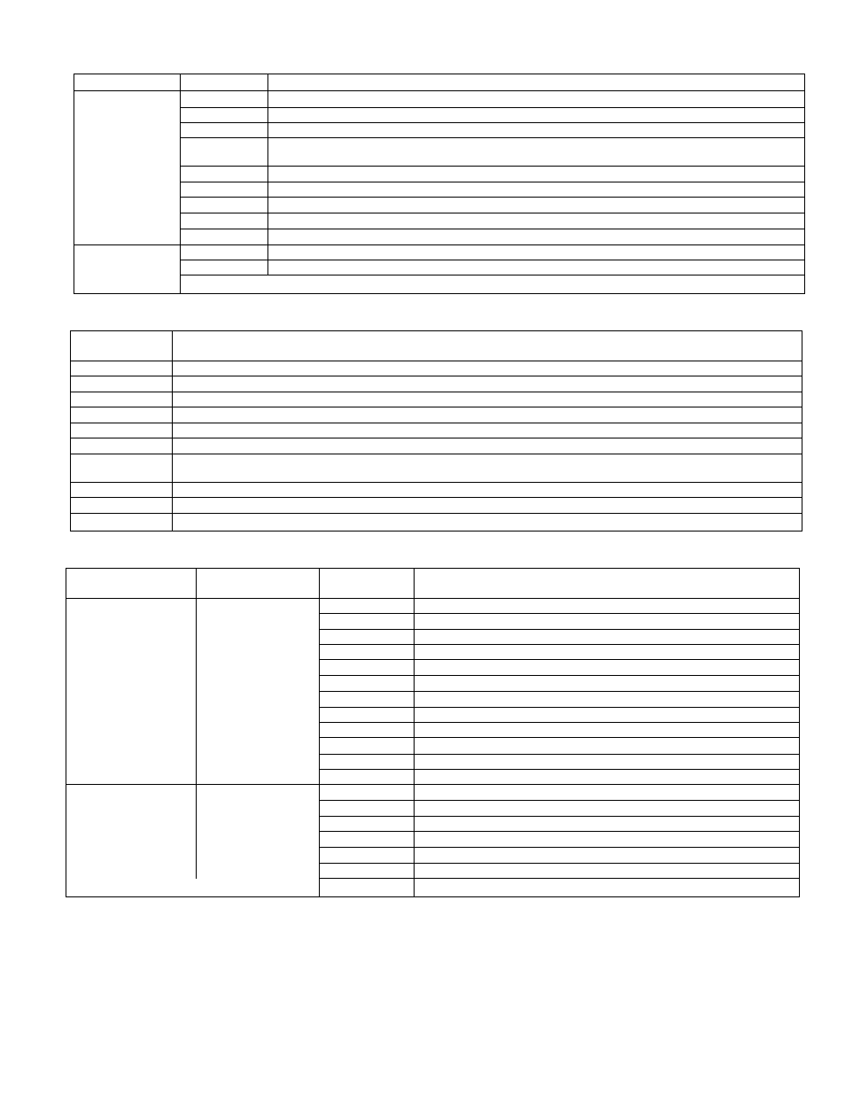
TABLE
3—MALE/FEMALE
QUICK-CONNECT TERMINALS
SIZE FEMALE
SIZE MALE
DESCRIPTION
M2
Motor line voltage connection (230 vac 60 Hz)
T3
Transformer line voltage connection (230 vac go Hz)
T2
Transfomior tap storage terminal for 208-vac lead
0.250 X 0.032
SEC1
Secondary connection from transformer (24 vac)
This connection is common to chassis ground through sydet marked GROUND SCREW REQUIRED,
SEC2
Secondary connection from transformer (24 vac)
HUM1
Low voltage ground for humidifier option (24 vdc)
HUM2
Low voltage output for humidifier option (24 vdc)
AUX1
Low voltage ground for auxiliary option (24 vdc)
AUX2
Low voltage output for auxiliary option (24 vdc)
Ml
Common connection to blower motor
0.187 X 0.032
T1
Common connection for transformer
REd I
Common to R screw terminal and SEC2
TABLE 4™C0NNECTI0NS ON SINGLE BARRIER S
tr
IR MOUNTED, CROSS SLOTTED, CAPTIVE BINDING HEAD
SCREW
TERMINAL
DESCRIPTION
W2
Connection fbr W2 signal from thermostat
W3
Connection for W3 signal from outdoor thermostat
E
Connection for E signal from thermostat
Y/Y2
Connection for Y signal from thermostat
G
Connection for G signal from thermostat
0
Connection for 0 signal from thermostat
L
This connection Is a field termination for use in connecting L lines of thermostat and outdoor unit together. Thare is no
connection of this terminal with control circuity.
Y1
Connaction for low-speed compressor operation
R
Connection for R signal to tharmostat (24 vac)
C
Connection for C terminal to thermostat (24 vac common)
TABLE 5—CONNECTIONS AND CONNECTOR
TYPE
CONNECTION
TYPE
CONNECTOR
PIN NO.
DESCRIPTION
Pin 1
Common to E screw terminal
Pin 2
Common to W2 screw terminal
Pin 3
Common to C screw terminal, SEC1 terminal, and chassis ground
Pin 4
Common to C screw terminal, SEC1 terminal, and chassis ground
Pins
No connection
Heater
12-Pln
Pin 6
Common to W3 scraw terminal
Connection
Pin?
Common to M2 and T3 quick-connects, 230 vac input
Plh'B
No connection
Pin 9
Common to Mi and T1 quick-connects, 230 vac input
Pin 10
No connection
Pin 11
No connection
Pin 12
No connection
Pin 1
Diode OR output of E or W3 or W2 thermostat signals
Pin 2
Thermostat G signal
Pin3
Common to C, SECI, and chassis ground
ICM2 Motor
7-Pin Header
Pin 4
Common to C, SEC1, and chassis ground
Pins
Common to R and SEC2 (via 5-amp fuse)
Pin 6
Thermostat Yrir2 signal
1
Pin?
Thermostat Y1 signal
receiving correct voltage, replace sequencer. If sequencer is
dosing, check high-voltage wiring as discussed in items 1
and 2.
IF THERE ARE BLOWN DIODES:
If diodes are blown, it is probable electric heater plug is miswired.
Correct miswiring.
NOTE: Board will need to be replaced if diode is bad.
IF TRACES ARE OVERHEATED ON BACK OF PQB;
Usually whenever there js a trace blown on PCB, it means cither
there has been a high-voltage short or high voltage has been
applied to low-voltage circuit. This can be prevented by making
sure PCB is wired correctly before PCB has power applied to it.
-11-