I. problems affecting txv, A. low suction pressure, B. high suction pressure – Bryant FA4A User Manual
Page 15: Piston body cleaning or replacement, Liquid tube strainer, Coiucondensate pan removal and replacement, I. a-coil units, Piston body cleaning or repl^'cement -16, Utc tech pub
Attention! The text in this document has been recognized automatically. To view the original document, you can use the "Original mode".
A D G / 1 4 / 2 0 0 8 / T H U 0 3 :
UTC TECH PUB
F A X N o , 3 1 7 2 4 0 5 6 6 2
P , 0 1 5
The standard TXV is a bi-flow meterijig device that is used in
condensing and heat pump systems to adjust to changing load
conditions by maintaining a preset superheat temperature at outlet
of evaporator coil. The volume of refrigerant metered through
valve scat is dependent upon the following:
1. Superheat temperature sensed by sensing bulb on suction
tube at Outlet of evaporator coil. As long as this bulb
contains some liquid refrigerantj this temperature is con
verted into pressure pushing downward on the diaphragm,
which opens the valve via push rods,
2. The Suction pressure at outlet of evaporator coil is trans
ferred via the external equalizer tube to underside
of
diaphragm.
3. The needle valve On pin carrier is spring-loaded, which also
exerts pressure on underside of diaphragm via push rods,
which doses valve. Therefore, bulb pressure equals evapo
rator pressure at outlet of coil plus spring pressure. If load
increases, temperature increases at bulb, which increases
pressure on topside of diaphragm, which pushes pin carrier
away from seal, opening valve and increasing flow of
re:frigerant. The increased refrigerant flow causes increased
leaving evaporator pressure which is transferred via the
equalizer tube to underside of diaphragm, with which the
pin carrier spring pressure closes valve. The refrigerant
flow is effectively stabilised to load demand with negligible
change in superheat.
The bi-flow TXV is used on split system heat pumps. In cooling
mode, TXV operates the same as a standard TXV previously
explained. However, when system is switched to heating mode of
operation, refrigerant ,flow is reversed. The bi"flow TXV has an
additional internal cheeje valve and external tubing. These addi
tions allow refrigerant to bypass TXV when refrigerant flow is
reversed with only a 1- to 2-psig pressure drop through device.
When heat pump switches to defiost mode, refrigerant flows
through a completely open (not throttled) TXV, The bulb Senses
the residual heat of outlet tube of coil that had been operating in
heating mode (about S5“F and 155 psig). This temporary, not
throttled valve, decreases indoor pressure drop, which in turn .
increases refrigerant flow rate, decreases overall defrost time, and
enhances defrost efficiency.
I.
PROBLEMS AFFECTING TXV
A. Low Suction Pressure
1. Restriction in TXV
2.
Low
refrigerant charge
3. Low indoor load
4. Low evaporator airflow
B.
High Suction Pressure
1. Overcharging
2, Sensing bulb not secure to vapor tube
3, High indoor load
4. Large evaporator face area
When installing or removing TXV, wrap TXV with a wet cloth.
When reattaching TXV, make sure sensing bulb is in good thermal
contact with suction tube.
PISTON BODY CLEANING OR REPLACEMENT
A
CAUTION; Do not vent refrigerant to atmosphere. Re^
cover during system repair or final unit disposal.
CAUTION:
Damage may occur to the scroll compressor
A
if operated at a negative suction pressure during a system
pumpdown.
1. Pump down outdoor unit. Close service valves at outdoor
unit.
2. Recover remaining refrigerant from tubing and coil through
gage port On vapor-tube service valve.
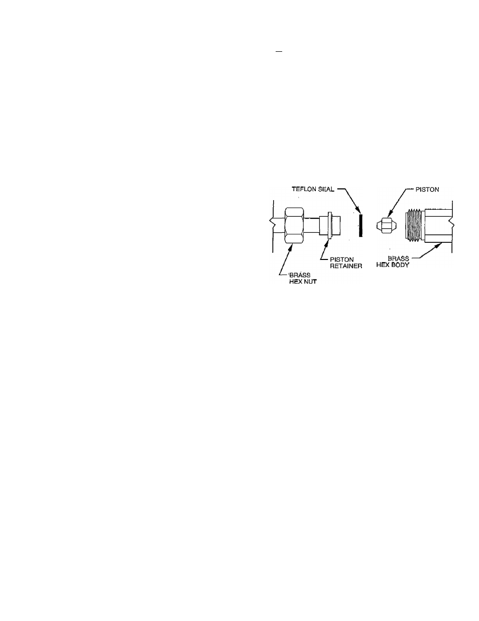
3. Disconnect refrigerant (liquid) tube from piston body, (See
Fig. 13.)
4. Avoid damaging seal ring or machined surfaces on piston,
bore, and retainer.
5. Using small wire with a hook on end of it, remove piston
from body.
A
A93530
Fig. 13—Refrigerant Flow-Control Device
(For FA, FB, and FF)
CAUTION: When cleaning the pi?ton orifice, be careful
not to scratch or enlarge the opening, as this will affect
operation.
6. Install new or cleaned piston into body.
7. Replace seal ring on retainer.
S. Reconnect refrigerant tube to piston body,
9. Pressurize tubing and coil, then leak check.
10. Evacuate tubing and, coil as necessary.
A
CAUTION:
Use a backup wrench and do not over
tighten, as deformation of the piston body will occur,
Causing the piston to lodge in a partially open or closed
position.
LIQUID TUBE STRAINER
The TXV and refrigerant flow-control device is protected on the
indoor coil by a wire mesh strainer. It is located inside the 3/S-in.
liquid tube at field braze joint just outside unit casing. Access to
strainer is through field braze joint.
COIUCONDENSATE PAN REMOVAL
AND
replacement
I. A-COIL UNITS
If it is determined that system does not have leaks and refiigerant
is not contaminated, proceed as follows:
1, Recover system refrigerant.
^
15
-