Fig. 21—checking pulley alignment and tightness, Ii, maintenance, A, return-air filter – Bryant FA4A User Manual
Page 24: B. coil, drain pan, and condensate drain, I. pcb component layout, description, and function
Attention! The text in this document has been recognized automatically. To view the original document, you can use the "Original mode".
A U G / 1 4 / 2 0 0 8 / T H U 0 3 : 5 1
UTC TECH PUB
:}
UNE
GROUNO
LEAD
A91151
Fig. 20—Wiring Schematic
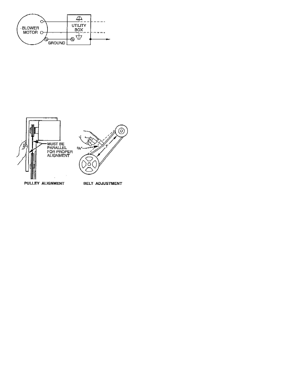
firmly. Lock adjusting bolt in position after adjustment is made.
Align pulley grooves by locating motpr pujley on motor shaft or by
moving entire motor along motor mounting bracket. Adjust blower
speed by loosening setscrew in outer (moveable) pulley face and
turning this face (half or full turns) so that adjusting setscrew is
positioned precisely over the flat on pulley hub. Speed is reduced
by adjusting pulley faces so they are further apart; speeds is
increased with faces closer together. Cheek pulley setscrews and
bolts.
A91150
Fig. 21—Checking Pulley Alignment and Tightness
D. Cleaning or Replacing Refrigerant Flow-Control
Device
Refer to Fig. 19 and instructions given in FD3A Service and
Troubleshooting section above,
II, MAINTENANCE
A
A
WARNING: Disconnect electrical power to all circuits
before servicing unit. Failure to do SO may result in
personal injury from dcctrical shock or moving parts.
WARNING:
As with any mechamcaj equipment, per
sonal injury can result fi'om sharp metal edges. Be careful
when removing parts.
A, Return-Air Filter
To clean or replace sir filter, remove screws and filter access door.
Slide out filter. For washable type filters, clean with hot soapy
water. Rinse clean and let dry.
New filters are available from a local distributor. Place filter in slot
with filter arrow facing direction of airflow. Replace filter access
doors with screws previously removed.
A
CAUTION:
Never operate unit without a filter or with
filter access door removed. Damage to blower motor may
result-
B. Coil, Drain Pan, and Condensate Drain
F A X N o , 3 1 7 2 4 0 5 6 6 2
A
CAUTION:
Discounect electrical power before remov
ing any access panels or electrical shock may result.
The coil is easily cleaned when dry. To check or clean coil, remove
coil access panel. If coil is coated with dirt or lint, vacuum with a
soft brush attachment.
Be careful not to bend fins. If coil is coated with oil or grease, it
may be cleaned with mild detergent and water solution. Rinse coil
with dean water. Be carciiil not to splash water on insulation or
filter.
Check drain pan and condensate.drain at same time cooling, coil is
checked. Clean drain pan and condensate drain by removing any
foreign matter from pan. Check for rust and holes. Flush pan and
drain tube- with clear water. If drain is restricted, clean with
high-pressure water. If this does not work.
Use
a plumbery's snake
or similar probe device. Rcpitch drain pan to promote proper
drainage.
FA4A, FB4A. AND FC4B SMART HEAT CIRCUIT BOARD
FUNCTION AND TROUBLESHOOTING
I. PCB COMPONENT LAYOUT, DESCRIPTION, AND
FUNCTION
NOTE:
All voltages are AC unless otherwise specified.
1. The low-voltage terminal board is used to coimeot indoor
thermostat to low, 24-v side of transformer and to serve as
a junction between indoor thermostat and outdoor seefion.
a, R terminal is used to connect secondary side of trans
former to thermostat and outdoor unit. R is fused.
b. C terminal is used to connect transformer secondary
common for thermostat and outdoor unit.
c, Y terminal provides input signal from thermostat signal
ing heat pump operation,
d. G terminal provitJes input signal from thermostat signal
ing cdnUiiiiOus fan 'dperatidn,
c,
O terminal provides input and junction terminal for
reversing vaive sign'd.
f, W2D terminal provides input from outdoor unit (heat
pump) signaling control board that heat pump is in
defrost.
g. W2T terminal provides input from thermostat signaling
for supplemental or emergency heat.
h. W3 terminal provides input from outdoor thermostat.
W3 and W2T are factory connected by JWl. Thl^ input
is used only if an outdoor thermostat is required by local
codes.
i, Y(, rerinihar provides output from control board to
energize outdoor unit (heat pump) contactor.
2. Jumper wires (JWl and JW2). (See Fig. 22.)
a. JWl connects W2T to W3 to limit staging of electric
heat with use of an outdoor thermostat. See Table 7 for
staging. Smart Heat PCB controls staging to the extent
that this feature is unnecessary unless required by local
codes
Or
regulations.
b. Cutting JW2 sets Smart Heat PCB in efficiency mods.
With JW2 cut, there is no loss of performance due to
reduced indoor blower speed when heat pump is oper
ating near balance point. This jumper may need to be cut
if selected cooling fan speed is the same as required
minimum motor LO speed tap selection. With JW2 cut,
fan terminal LO becomes a dummy terminal.
-
24
-